Power Systems
Transmission and Distribution
Voltage and Frequency Control
Questions mapped to Voltage and Frequency Control under Transmission and Distribution.
18
Total0
Attempted0
Correct0
IncorrectConsider a distribution feeder, with ratio of 5. At the receiving end, a 350 kVA load is connected. The maximum voltage drop will occur from the sending end to the receiving end, when the power factor of the load is ________ (round off to three decimal places).

Sign in to see the solution
Log in to view the explanation, track your attempts, and keep your progress.
Sign in to UnlockThe inductance and capacitance of a 400kV, three-phase, 50 Hz lossless transmission line are 1.6 mH/km/phase and 10 mF/km/phase respectively. The sending end voltage is maintained at 400kV. To maintain a voltage of 400kV at the receiving end, when the line is delivering 300MW load, the shunt compensation required is
Sign in to see the solution
Log in to view the explanation, track your attempts, and keep your progress.
Sign in to UnlockShunt reactors are sometimes used in high voltage transmission systems to
Sign in to see the solution
Log in to view the explanation, track your attempts, and keep your progress.
Sign in to UnlockFor enhancing the power transmission in a long EHV transmission line, the most preferred method is to connect a
Sign in to see the solution
Log in to view the explanation, track your attempts, and keep your progress.
Sign in to UnlockA 50Hz synchronous generator is initially connected to a long lossless transmission line which is open circuited at the receiving end. With the field voltage held constant, the generator is disconnected from the transmission line. Which of the following may be said about the steady state terminal voltage and field current of the generator?

Sign in to see the solution
Log in to view the explanation, track your attempts, and keep your progress.
Sign in to UnlockThree generators are feeding a load of 100 MW. The details of the generators are
Rating (MW) | Efficiency (%) | Regulation (p.u.) on 100 MAVA base | |
Generator-1 | 100 | 20 | 0.02 |
Generator-2 | 100 | 30 | 0.04 |
Generator-3 | 100 | 40 | 0.03 |
In the event of increased load power demand, which of the following will happen?
Sign in to see the solution
Log in to view the explanation, track your attempts, and keep your progress.
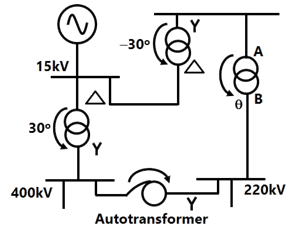
Sign in to UnlockConsider the transformer connections in a part of a power system shown in the figure. The nature of transformer connections and phase shifts are indicated for all but one transformer. Which of the following connections, and the corresponding phase shift , should be used for the transformer between A and B?





Sign in to see the solution
Log in to view the explanation, track your attempts, and keep your progress.
Sign in to UnlockA 230 V (Phase). 50 Hz, three-phase, 4-wire system has a phase sequence ABC. A unity power-factor load of 4 kW is connected between phase A and neutral N. It is desired to achieve zero neutral current through the use of a pure inductor and a pure capacitor in the other two phases. The value of inductor and capacitor is
Sign in to see the solution
Log in to view the explanation, track your attempts, and keep your progress.
Sign in to UnlockThe rated voltage of a 3-phase power system is given as
Sign in to see the solution
Log in to view the explanation, track your attempts, and keep your progress.
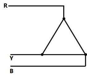
Sign in to UnlockThe phase sequence of the 3-phase system shown in Figure is
Sign in to see the solution
Log in to view the explanation, track your attempts, and keep your progress.
Sign in to UnlockA new generator having [equivalent to (1.212+j0.70) p.u. and synchronous reactanceof 1.0 p.u. on the system base, is to be connected to a bus having voltage in the existing power system. This existing power system can be represented by Thevenin’s voltage in series with Thevenin’s impedance . The magnitude of the bus voltage of the system in pu will be






Sign in to see the solution
Log in to view the explanation, track your attempts, and keep your progress.
Sign in to UnlockConsider a power system with three identical generators. The transmission losses are negligible. One generator () has a speed governor which maintains its speed constant at the rated value, while the other generators (and ) have governors with a drop of 5%.If the load of the system is increased, then in steady state.



Generation of and is increased equally while generation of is unchanged.
Generation of alone is increased while generation of and is unchanged.
Generation of , and is increased equally.
Generation of , and is increased in the ratio 0.5:0.25:0.25.
Sign in to see the solution
Log in to view the explanation, track your attempts, and keep your progress.
Sign in to UnlockA transmission line has a total series reactance of 0.2 pu. Reactive power compensation is applied at the midpoint of the line and it is controlled such that the midpoint voltage of the transmission line is always maintained at 0.98 pu. If voltage at both ends of the line are maintained at 1.0 pu, then the steady state power transfer limit of the transmission line is
Sign in to see the solution
Log in to view the explanation, track your attempts, and keep your progress.
Sign in to UnlockA power system has two synchronous generators. The Governor-turbine characteristics corresponding to the generators are. Where f denotes the system frequency in Hz, and and are, respectively, the power outputs (in MW) of turbines 1 and 2 assuming the generators and transmission network to be lossless, the system frequency for a total load of 400 MW is



Sign in to see the solution
Log in to view the explanation, track your attempts, and keep your progress.
Sign in to UnlockSeries capacitive compensation in EHV transmission lines is used to
Sign in to see the solution
Log in to view the explanation, track your attempts, and keep your progress.
Sign in to UnlockA shunt reactor of 100MVAr is operated at 98% of its rated voltage and at 96% of its rated frequency. The reactive power absorbed by the reactor is:
Sign in to see the solution
Log in to view the explanation, track your attempts, and keep your progress.
Sign in to UnlockTwo power systems A and B each having a regulation (R) of 0.05 p.u. on their respectively capacity bases and a stiffness (damping coefficient) of 0.75 p.u. are connected through a tie-line, initially carrying no power. The capacity of system A is 2000 MW and that of system B is 3000MW. If there is an increase in load of 200MW in system A, what is the change in the steady-state frequency and power transfer?
Sign in to see the solution
Log in to view the explanation, track your attempts, and keep your progress.
Sign in to UnlockIn a 400 kV network, 360 kV is recorded at a 400 kV bus. The reactive power absorbed by a shunt rated for 50 MVAR, 400 kV connected at the bus is
Sign in to see the solution
Log in to view the explanation, track your attempts, and keep your progress.
Sign in to Unlock