Power Electronics
Chopper
Buck Converter
Questions mapped to Buck Converter under Chopper.
28
Total0
Attempted0
Correct0
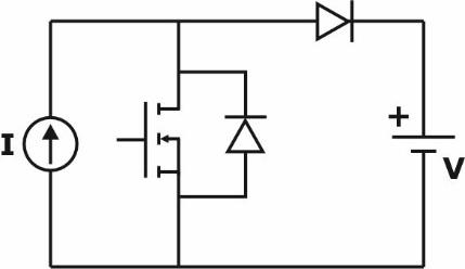
IncorrectIn the circuit with ideal devices, the power MOSFET is operated with a duty cycle of 0.4 in a switching cycle with and . The power delivered by the current source, in W, is __________ (round off to the nearest integer).


Sign in to see the solution
Log in to view the explanation, track your attempts, and keep your progress.
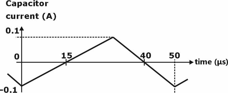
Sign in to UnlockThe steady state capacitor current of a conventional DC-DC buck converter, working in CCM, is shown in one switching cycle. If the input voltage is 30 V, the value of the inductor used, in mH, is ________ (round off to one decimal place).
Sign in to see the solution
Log in to view the explanation, track your attempts, and keep your progress.
Sign in to UnlockThe chopper circuit shown in figure (i) feeds power to a 5 A DC constant current source. The switching frequency of the chopper is . All the components can be assumed to be ideal. The gate signals of switches and are shown in figure (ii). Average voltage across the 5 A current source is



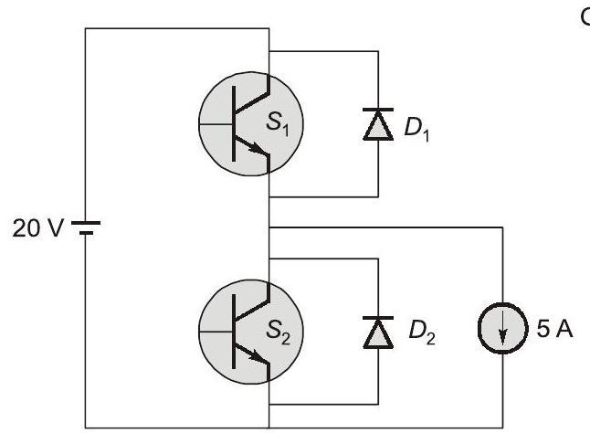
Fig. (i)
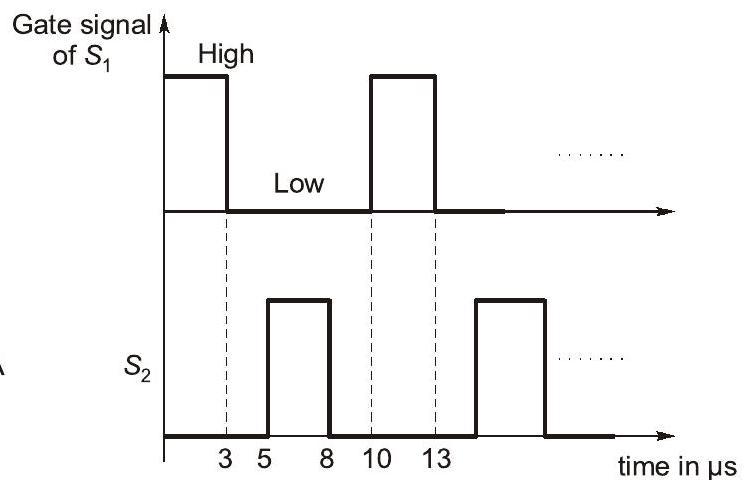
Fig. (ii)
Sign in to see the solution
Log in to view the explanation, track your attempts, and keep your progress.
Sign in to UnlockIn the DC-DC converter circuit shown, switch Q is switched at a frequency of 10 kHz with a duty ratio of 0.6. All components of the circuit are ideal, and the initial current in the inductor is zero. Energy stored in the inductor in mJ (rounded off to 2 decimal places) at the end of 10 complete switching cycles is _________.

Sign in to see the solution
Log in to view the explanation, track your attempts, and keep your progress.
Sign in to UnlockA DC-DC buck converter operates in continuous conduction mode. It has 48 V input voltage, and it feeds a resistive load of 24 Ω. The switching frequency of the converter is 250 Hz. If switch-on duration is 1 ms, the load power is
Sign in to see the solution
Log in to view the explanation, track your attempts, and keep your progress.
Sign in to UnlockThe figure shows two buck converters connected in parallel. The common input DC voltage for the converters has a value of 100V. The converters have inductors of identical value. The load resistance is . The capacitor voltage has negligible ripple. Both converters operate in the continuous conduction mode. The switching frequency is 1 kHz, and the switch control signals are as shown. The circuit operates in the steady state. Assuming that the converters share the load equally, the average value of, the current of switch S1 (in Ampere), is ______ (up to 2 decimal places).




Sign in to see the solution
Log in to view the explanation, track your attempts, and keep your progress.
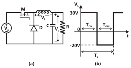
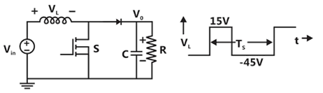
Sign in to UnlockA buck converter, as shown in Figure (a) below, is working in steady state. The output voltage and the inductor current can be assumed to be ripple free. Figure (b) shows the inductor voltage during a complete switching interval. Assuming all devices are ideal, the duty cycle of the buck converter is ___________.

Sign in to see the solution
Log in to view the explanation, track your attempts, and keep your progress.
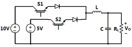
Sign in to UnlockThe circuit shown is meant to supply a resistive load from separate DC voltage sources. The switches S1 and S2 are controlled so that only one of them is ON at any instant. S1 is turned on for 0.2 ms and S2 is turned on for 0.3 ms in a 0.5 ms switching cycle time period. Assuming continuous conduction of the inductor current and negligible ripple on the capacitor voltage, the outputs voltage (in Volt) across is _____.


Sign in to see the solution
Log in to view the explanation, track your attempts, and keep your progress.
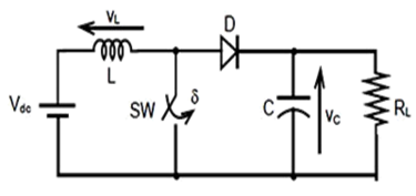
Sign in to UnlockA self-commutating switch SW, operated at duty cycle is used to control the load voltage as shown in the figure. Under steady state operating conditions, the average voltage across the inductor and the capacitor respectively, are

and


and

and

and
Sign in to see the solution
Log in to view the explanation, track your attempts, and keep your progress.
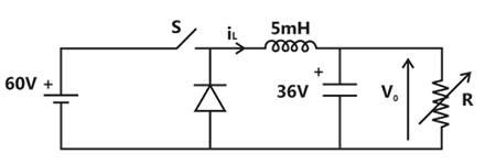
Sign in to UnlockA buck converter feeding a variable load is shown in the figure. The switching frequency of the switch is 100 kHz and the duty ratio is 0.6. The output voltage is 36 V. Assume that all the components are ideal, and that the output voltage is ripple-free. The value of R (in Ohm) that will make the inductor current () just continuous is __________.


Sign in to see the solution
Log in to view the explanation, track your attempts, and keep your progress.
Sign in to UnlockFor switching converter shown in the following figure, assume steady-state operation. Also assume that the components are ideal, the inductor current is always positive and continuous and switching period is. If the voltage is as shown, the duty cycle of the switch S is______.


Sign in to see the solution
Log in to view the explanation, track your attempts, and keep your progress.
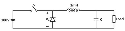
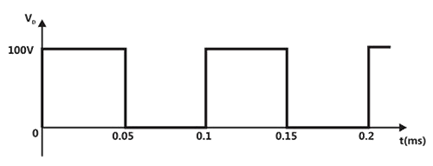
Sign in to UnlockFigure (i) shows the circuit diagram of a chopper. The switch S in the circuit in the figure (i) is switched such that the voltage across the diode has the wave shape as shown in figure (ii). The capacitance C is large so that the voltage across it is constant. If switch S and the diode are ideal, the peak to peak ripple (in A) in the inductor current is ______________

Sign in to see the solution
Log in to view the explanation, track your attempts, and keep your progress.
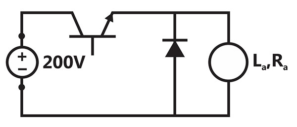
Sign in to UnlockThe separately excited dc motor in the figure below has a rated armature current of 20A and a rated armature voltage of 150 V. An ideal chopper switching at 5 kHz is used to control the armature voltage. If , , neglecting armature reaction, the duty ratio of the chopper to obtain 50% of the rated torque at the rated speed and the rated field current is


Sign in to see the solution
Log in to view the explanation, track your attempts, and keep your progress.
Sign in to UnlockIn the figure shown below, the chopper feeds a resistive load from a battery source. MOSFET Q is switched at 250 kHz, with a duty ratio of 0.4. All elements of the circuit are assumed to be ideal.
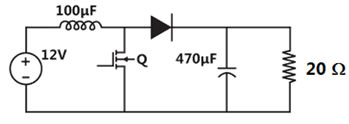
The average source current in Amps in steady-state is
Sign in to see the solution
Log in to view the explanation, track your attempts, and keep your progress.
Sign in to UnlockIn the figure shown below, the chopper feeds a resistive load from a battery source. MOSFET Q is switched at 250 kHz, with a duty ratio of 0.4. All elements of the circuit are assumed to be ideal.
The PEAK-TO-PEAK source current ripple in Amps is
Sign in to see the solution
Log in to view the explanation, track your attempts, and keep your progress.
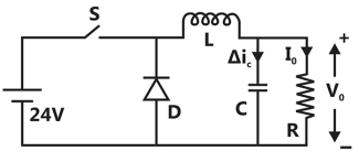
Sign in to UnlockIn the circuit shown, an ideal switch S is operated at 100kHz with a duty ratio of 50%. Given that is 1.6A peak-to-peak and is 5 A dc, the peak current in S is


Sign in to see the solution
Log in to view the explanation, track your attempts, and keep your progress.
Sign in to UnlockFigure shows a step-down chopper switched at 1 KHz with a duty ratio D = 0.5. The peak-peak ripple in the load current is close to

Sign in to see the solution
Log in to view the explanation, track your attempts, and keep your progress.
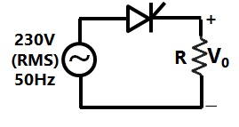
Sign in to UnlockConsider a phase controlled converter shown in Figure. The thyristor is fired at an angle α in every positive half cycle of the input voltage. If the peak value of the instantaneous output voltage equals 230 V, the firing angle α is close to
Sign in to see the solution
Log in to view the explanation, track your attempts, and keep your progress.
Sign in to UnlockFigure shows a chopper operating from a 100 V dc input. The duty ratio of the main switch S is 0.8. The load is sufficiently inductive so that the load current is ripple free. The average current through the diode D under steady state is

Sign in to see the solution
Log in to view the explanation, track your attempts, and keep your progress.
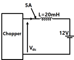
Sign in to UnlockA chopper is employed to charge a battery as shown in Figure. The charging current is 5A. The duty ratio is 0.2. The chopper output voltage is also shown in Figure. The peak-to-peak ripple current in the charging current is

Sign in to see the solution
Log in to view the explanation, track your attempts, and keep your progress.
Sign in to UnlockA step down chopper is operated in the continuous conduction mode in steady state with a constant duty ratio D. If is the magnitude of the dc output voltage and if is the magnitude of the dc input voltage, the ratio is given by



D
1− D


Sign in to see the solution
Log in to view the explanation, track your attempts, and keep your progress.
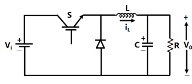
Sign in to UnlockIn the chopper circuit shown in Figure the input dc voltage has a constant value, the output voltage is assumed ripple-free. The switch S is operated with a switching time period T and a duty ratio D. what is the value of D at the boundary of continuous and discontinuous conduction of the inductor current ?







Sign in to see the solution
Log in to view the explanation, track your attempts, and keep your progress.
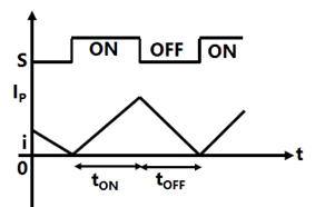
Sign in to UnlockIn Figure, the ideal switch S is switched on and off with a switching frequency f = 10 kHz. The switching time period is. The circuit is operated in steady state at the boundary of continuous and discontinuous conduction, so that the inductor current I is as shown in Figure. Find

(a) The on-time of the switch.

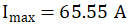
(b) The value of the peak current.





Sign in to see the solution
Log in to view the explanation, track your attempts, and keep your progress.
Sign in to UnlockA step down chopper operates from a dc voltage source and feeds a dc motor armature with a back emf . From oscilloscope traces, it is found that the current increases for time, falls to zero over time, and remains zero for time, in every chopping cycle. Then the average dc voltage across the freewheeling diode is:









Sign in to see the solution
Log in to view the explanation, track your attempts, and keep your progress.
Sign in to UnlockA dc to dc transistor chopper supplied from a fixed voltage dc source feeds a fixed resistive-inductive load and a free-wheeling diode. The chopper operates at 1 kHz and 50% duty cycle. Without changing the value of the average dc current through the load, if it is desired to reduce the ripple content of load current, the control action needed will be:
Sign in to see the solution
Log in to view the explanation, track your attempts, and keep your progress.
Sign in to UnlockA chopper operating at a fixed frequency is feeding an R-L load. As the duty ratio of the chopper is increased from 25% to 75%, the ripple in the load current
Sign in to see the solution
Log in to view the explanation, track your attempts, and keep your progress.
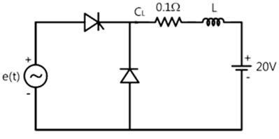
Sign in to UnlockIn the circuit shown in figure, L is large and the average value of ‘i’ is 100A. The thyristor is gated in the ________________ half cycle of ‘e’ at a delay angle equal to __________


Sign in to see the solution
Log in to view the explanation, track your attempts, and keep your progress.
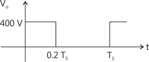
Sign in to UnlockFigure shows the circuit schematic of a chopper driven, separately excited d.c. motor. The single-pole double-throw switch operates with a switching period is 0.2. The motor may be assumed lossless, with an armature inductance of 10 mH. The motor draws an average current of 20A at a constant back emf of 80V, under steady state.

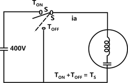
(a) Sketch and label the voltage waveform of the chopper for one switching period

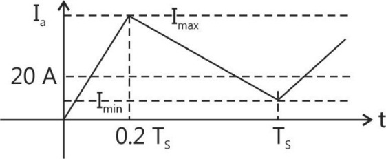
(b) Sketch and label the motor current for one switching period.

(c) Evaluate the peak-to-peak current ripple of the motor.


Sign in to see the solution
Log in to view the explanation, track your attempts, and keep your progress.
Sign in to Unlock