Digital Electronics
Combinational Circuits
Multiplexer and Demultiplexer
Questions mapped to Multiplexer and Demultiplexer under Combinational Circuits.
8
Total0
Attempted0
Correct0
IncorrectTo obtain the Boolean function , the inputs in the figure should be



Sign in to see the solution
Log in to view the explanation, track your attempts, and keep your progress.
Sign in to UnlockConsider the following circuit which uses a 2-to-1 multiplexer as shown in the figure below. The Boolean expression for output F in terms of A and B is
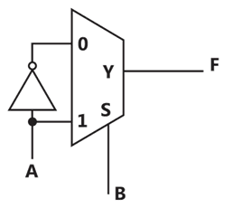


A + B

Sign in to see the solution
Log in to view the explanation, track your attempts, and keep your progress.
Sign in to UnlockIn the 4 x 1 multiplexer, the output F is given by. Find the required input .


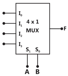
Sign in to see the solution
Log in to view the explanation, track your attempts, and keep your progress.
Sign in to UnlockA Boolean function is to be implemented using an 8 x 1 multiplexer (A is MSB), The inputs ABC are connected to the select inputs of the multiplexer respectively.


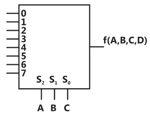
Which one of the following options gives the correct inputs to pins 0,1,2,3,4,5,6,7 in order?




Sign in to see the solution
Log in to view the explanation, track your attempts, and keep your progress.
Sign in to UnlockA 4 × 1 MUX is used to implement a 3-input Boolean function as shown in figure. The Boolean function F(A, B, C) implemented is
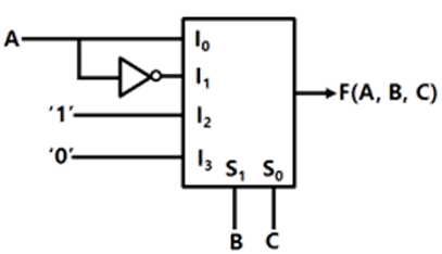




Sign in to see the solution
Log in to view the explanation, track your attempts, and keep your progress.
Sign in to UnlockFigure shows a 4 to 1 MUX to be used to implement the sum S of a 1-bit full adder with input bits P and Q and the carry input. Which of the following combinations of inputs to and of the MUX will realize the sum S?



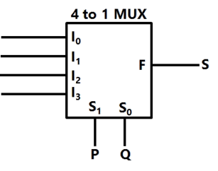




Sign in to see the solution
Log in to view the explanation, track your attempts, and keep your progress.
Sign in to UnlockThe output of the 4-to-1 MUX shown in figure is
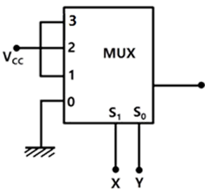




Sign in to see the solution
Log in to view the explanation, track your attempts, and keep your progress.
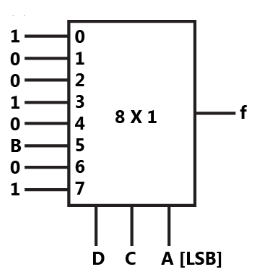
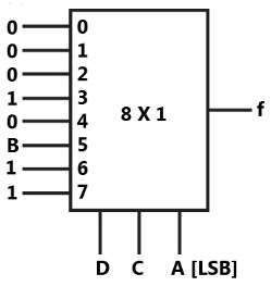
Sign in to UnlockThe logic function is to be realized using an 8 to 1 multiplexer shown in figure, using A, C and D as control inputs.

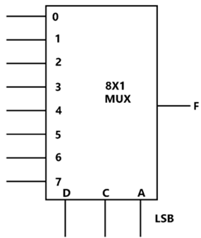
(a) Indicate the inputs to be applied at the terminals 0 to 7
(b) Can the function be realize using a 4 to 1 multiplexer? State YES or NO
(a)
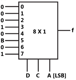
(b) No
(a)
(b) No
(a)
(b) Yes
(a)
(b) No
Sign in to see the solution
Log in to view the explanation, track your attempts, and keep your progress.
Sign in to Unlock