Power Systems
Fault Analysis
Per Unit System
Questions mapped to Per Unit System under Fault Analysis.
12
Total0
Attempted0
Correct0
IncorrectFive alternators each rated 5 MVA. 13.2 kV with 25% of reactance on its own base are connected in parallel to a busbar. The short-circuit level in MVA at the busbar is _____________.
Sign in to see the solution
Log in to view the explanation, track your attempts, and keep your progress.
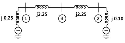
Sign in to UnlockTwo generator units G1 and G2 are connected by 15kV line with a bus at the mid-point as shown below.
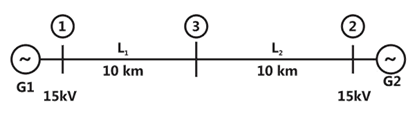
G1 = 250MVA, 15kV, positive sequence reactance X = 25% on its own base G2 = 100MVA, 15kV, positive sequence reactance X for the line = 0.225


For the above system, the positive sequence diagram with the p.u. values of the 100MVA common base is
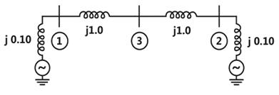
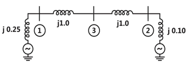
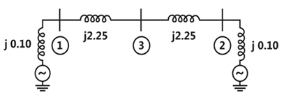
Sign in to see the solution
Log in to view the explanation, track your attempts, and keep your progress.
Sign in to UnlockFor the power system shown in the figure below. The specifications of the components are the following: [2010: 2 Marks]
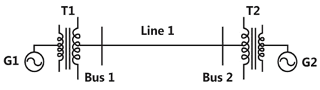





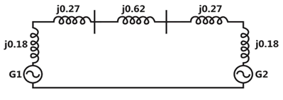
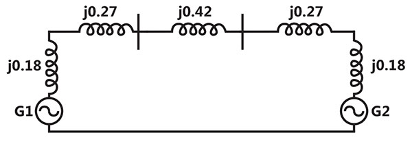
Choose 25kV as the base voltage at the generator G1 and 200 MVA as the MVA base. The impedance diagram is
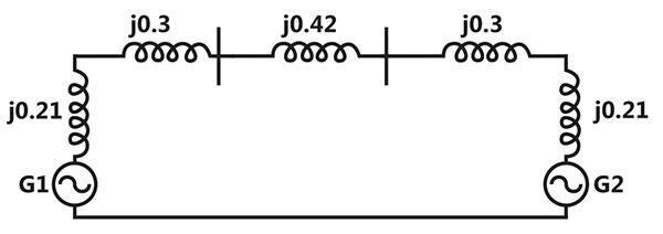
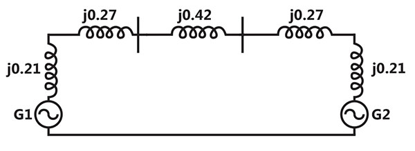
Sign in to see the solution
Log in to view the explanation, track your attempts, and keep your progress.
Sign in to UnlockA three phase balanced star connected voltage source with frequency to rad/s is connected to a star connected balanced load which is purely inductive. The instantaneous line currents and phase to neutral voltages are denoted by and respectively, and their RMS values are denoted by V and I.



If,

then the magnitude of R is
Sign in to see the solution
Log in to view the explanation, track your attempts, and keep your progress.
Sign in to UnlockA generator is connected through a 20 MVA 13.8/138 kV step-up transformer, to a transmission line. At the receiving end of the line a load is supplied through a step down transformer of 10 MVA, 138/69 kV rating. A 0.72 pu load, evaluated on load side transformer ratings as base values, is supplied from the above system. For system base values of 10 MVA and 69 kV in load circuit, the value of the load (in per unit) in generator circuit will be
Sign in to see the solution
Log in to view the explanation, track your attempts, and keep your progress.
Sign in to UnlockThe p.u. parameters for a 500 MVA machine on its own base are:
Inertia M = 20 p.u.; reactance X = 2 p.u.
The p.u. values of inertia and reactance on 100 MVA common base, respectively, are
Sign in to see the solution
Log in to view the explanation, track your attempts, and keep your progress.
Sign in to Unlockand are steady state d-axis synchronous reactance, transient d-axis reactance and sub-transient d-axis reactance of a synchronous machine respectively. Which of the following statement is true?






Sign in to see the solution
Log in to view the explanation, track your attempts, and keep your progress.
Sign in to UnlockA 75 MVA, 10 KV, synchronous generator has The value (in p.u.) on a base of 100 MVA, 11 KV is:


Sign in to see the solution
Log in to view the explanation, track your attempts, and keep your progress.
Sign in to UnlockFor given base voltage and base volt-amperes, the per unit impedance value of an element is x. What will be the per unit impedance value of this element when the voltage and volt ampere bases are both doubled?
Sign in to see the solution
Log in to view the explanation, track your attempts, and keep your progress.
Sign in to UnlockThe synchronous reactance of a 200 MVA, 10kV, 3-phase, 50Hz generator is 1.0p.u. at its own base. Its p.u. reactance at 100MVA, 20 kV base will be……
Sign in to see the solution
Log in to view the explanation, track your attempts, and keep your progress.
Sign in to UnlockThe system shown in figure feeds two loads-
(a) a factory load of 15 MVA consisting of induction motors and (b) a domestic load of 10MW at 0.8p.f. lagging at 6kV. If the induction motors are rated at 6 kV and take 5 times their rated current at zero p.f. at starting, calculate the dip in voltage at the domestic load bus bar when all the induction motors are started at the same time.
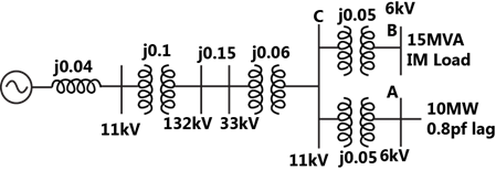
Sign in to see the solution
Log in to view the explanation, track your attempts, and keep your progress.
Sign in to UnlockA 100 MVA generator with 10% reactance and a 200 MVA generator with 8% reactance (reactances on their own bases) are connected as shown in figure. The fault level on bus 1 is to be restricted to 1500 MVA. Calculate, on 100 MVA base.
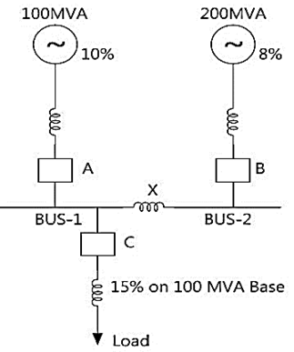
(i) The reactance of bus bar reactor X
(ii) Fault level of bus 2
(iii) MVA rating of circuit breaker C
Sign in to see the solution
Log in to view the explanation, track your attempts, and keep your progress.
Sign in to Unlock