Analog Electronics
OP-AMP and its Applications
Op-amp
Questions mapped to Op-amp under OP-AMP and its Applications.
8
Total0
Attempted0
Correct0
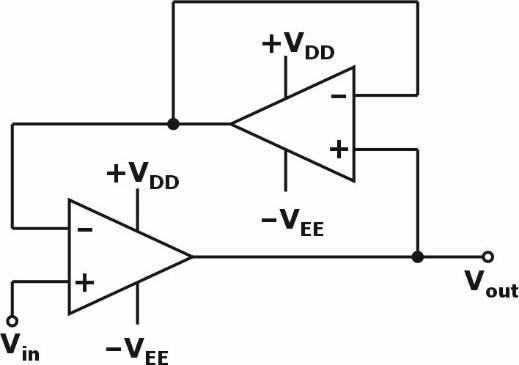
IncorrectAssuming ideal op-amps, the circuit represents a
Sign in to see the solution
Log in to view the explanation, track your attempts, and keep your progress.
Sign in to UnlockConsider the OP AMP based circuit shown in the figure. Ignore the conduction drops of diodes and . All the components are ideal and the breakdown voltage of the Zener is . Which of the following statements is true?



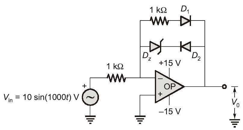
The maximum and minimum values of the output voltage are and , respectively.



The maximum and minimum values of the output voltage are and , respectively.


The maximum and minimum values of the output voltage are and , respectively.


The maximum and minimum values of the output voltage are and , respectively.
Sign in to see the solution
Log in to view the explanation, track your attempts, and keep your progress.
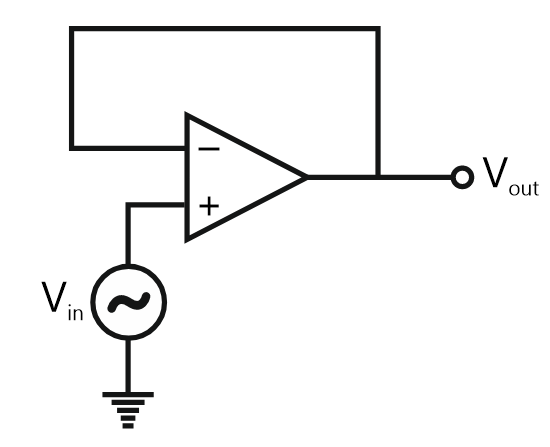
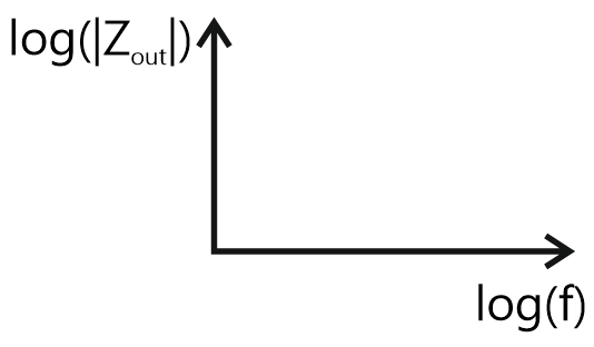
Sign in to UnlockThe output impedance of a non-ideal operational amplifier is denoted by The variation in the magnitude of with increasing frequency, f, in the circuit shown below, is best represented by

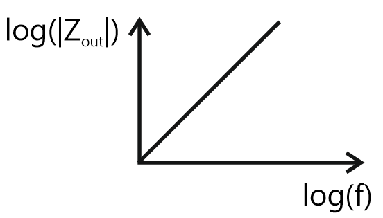
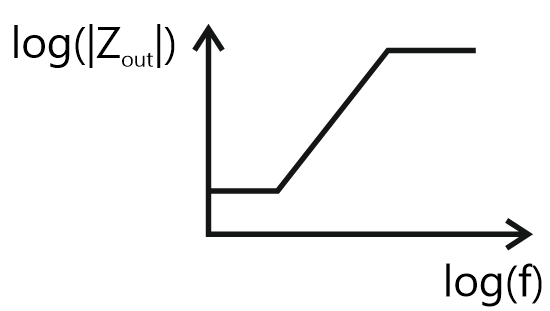
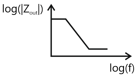
Sign in to see the solution
Log in to view the explanation, track your attempts, and keep your progress.
Sign in to UnlockThe approximate transfer characteristic for the circuit shown below with an ideal operational amplifier and diode will be
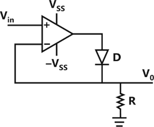
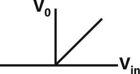
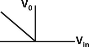
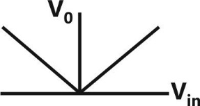
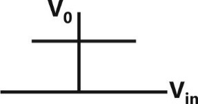
Sign in to see the solution
Log in to view the explanation, track your attempts, and keep your progress.
Sign in to UnlockThe saturation voltage of the ideal op – amp shown below is ±10V. The output voltage of the following circuit in the steady – state is

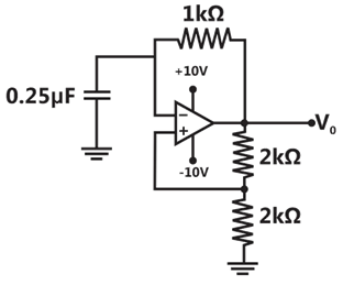
Sign in to see the solution
Log in to view the explanation, track your attempts, and keep your progress.
Sign in to UnlockAn op-amp having a slew rate of 62.8 V/µsec, is connected in a voltage follower configuration. If the maximum amplitude of the input sinusoid is 10V, then the minimum frequency at which the slew rate limited distortion would set in at the output is
Sign in to see the solution
Log in to view the explanation, track your attempts, and keep your progress.
Sign in to UnlockAn analog comparator is a high-gain amplifier whose output is always either in positive or in negative saturation. (True=1, False=0)
Sign in to see the solution
Log in to view the explanation, track your attempts, and keep your progress.
Sign in to UnlockGiven figure shows a two-stage small signal transistor feedback amplifier. Match the defective component (listed on the left hand side below) with its probable effect on the circuit (listed on the right hand side below)
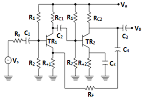
(a) Capacitor is open

(b) Capacitor is open

(c) Capacitor is open

(d) is shorted

(P) All dc voltages normal, increases marginally
(Q) Collector of is at ,



(R) All dc voltages normal, gain of stage increase decrease

(S) All dc voltages normal,

(T) All dc voltages normal, overall gain of the amplifier increases, increases
(U) No change
Sign in to see the solution
Log in to view the explanation, track your attempts, and keep your progress.
Sign in to Unlock