Power Systems
Power System Protection
Practice questions from Power System Protection.
40
Total0
Attempted0
Correct0
IncorrectFor the three-bus power system shown in the figure, the trip signals to the circuit breakers to are provided by overcurrent relays to , respectively, some of which have directional properties also. The necessary condition for the system to be protected for short circuit fault at any part of the system between bus 1 and the - loads with isolation of minimum portion of the network using minimum number of directional relays is


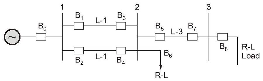
and are directional overcurrent relays blocking faults towards bus 2.


and are directional overcurrent relays blocking faults towards bus 2 and is directional overcurrent relay blocking faults towards bus 3.

and are directional overcurrent relays blocking faults towards Line 1 and Line 2, respectively, is directional overcurrent relay blocking faults towards ine 3 and is directional overcurrent relay blocking faults towards bus 2.

and are directional overcurrent relays blocking faults towards Line 1 and Line 2, respectively.
Explanation Locked!
Unlock this branch to view the explanation, track, bookmark and more.
Sign in to UnlockThe most commonly used relay, for the protection of an alternator against loss of excitation, is
Explanation Locked!
Unlock this branch to view the explanation, track, bookmark and more.
Sign in to UnlockThe total impedance of the secondary winding, leads, and burden of a 5A CT is . If the fault current is 20 times the rated primary current of the CT, the VA output of the CT is_____________.

Explanation Locked!
Unlock this branch to view the explanation, track, bookmark and more.
Sign in to UnlockIn a 132 kV system, the series inductance up to the point of circuit breaker location is 50 mH. The shunt capacitance at the circuit breaker terminal is 0.05. The critical value of resistance in ohms required to be connected across the circuit breaker contacts which will give no transient oscillation is __________.

Explanation Locked!
Unlock this branch to view the explanation, track, bookmark and more.
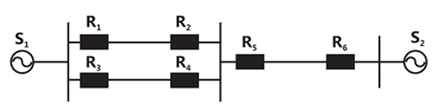
Sign in to UnlockA power system with two generators is shown in the figure below. The system (generators, buses and transmission lines) is protected by six over current relays to . Assuming a mix of directional and non directional relays at appropriate locations, the remote backup relays for are


Explanation Locked!
Unlock this branch to view the explanation, track, bookmark and more.
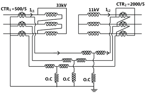
Sign in to UnlockA 3-phase transformer rated for 33 kV/11kV is connected in delta/star as shown in figure. The current transformers (CTs) on low and high voltage sides has a ratio of 500/5. Find the currents and, if the fault current is 300 A as shown in figure.


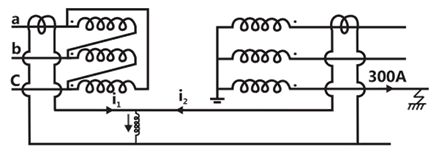
,


,


,
Explanation Locked!
Unlock this branch to view the explanation, track, bookmark and more.
Sign in to UnlockThe over current relays for the line protection and loads connected at the buses are shown in the figure.
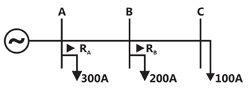
The relays are IDMT in nature having the characteristic

The maximum and minimum fault current at bus B are 2000A and 500A respectively. Assuming the time multiplier setting and plug setting for relay to be 0.1 and 5A respectively, the operating time of (in seconds) is _______________.

Explanation Locked!
Unlock this branch to view the explanation, track, bookmark and more.
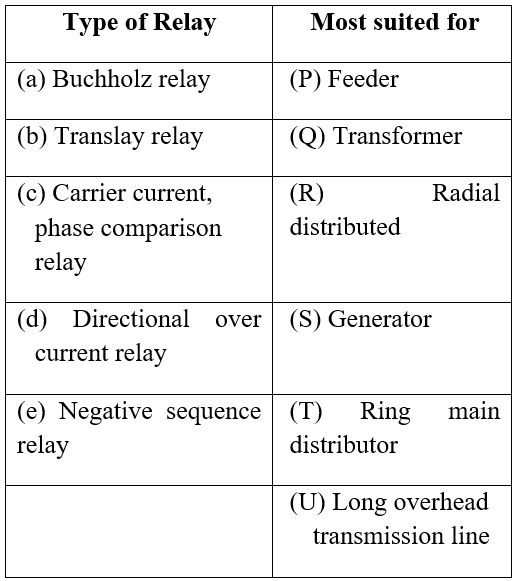
Sign in to UnlockA negative sequence relay is commonly used to protect
Explanation Locked!
Unlock this branch to view the explanation, track, bookmark and more.
Sign in to UnlockA three-phase 33kV oil circuit breaker is rated 1200A, 2000MVA 3s. The symmetrical breaking current is
Explanation Locked!
Unlock this branch to view the explanation, track, bookmark and more.
Sign in to UnlockConsider a stator winding of an alternator with an internal high-resistance ground fault. The current under the fault condition are as shown in the figure. The winding is protected using a differential current scheme with current transformers of ratio 400/5 A as shown. The current through the operating coil is
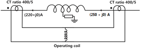
Explanation Locked!
Unlock this branch to view the explanation, track, bookmark and more.
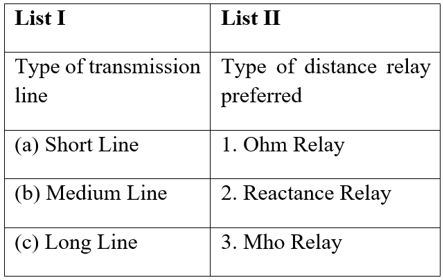
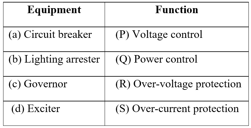
Sign in to UnlockMatch the items in List-I with the items in List-II and select the correct answer using the codes given below the lists
Explanation Locked!
Unlock this branch to view the explanation, track, bookmark and more.
Sign in to UnlockA two machine power system is shown below. Transmission line XY has positive sequence Impedance of and zero sequence impedance of .


An 'a' phase to ground fault with zero fault impedance occurs at the center of the transmission line. Bus voltage at X and line current from X to F for the phase 'a', are given by Volts and Amperes, respectively. Then, the impedance measured by the ground distance relay located at the terminal X of line XY will be given by


Explanation Locked!
Unlock this branch to view the explanation, track, bookmark and more.
Sign in to UnlockVoltage phasors at the two terminals of a transmission line of length 70 km have a magnitude of 1.0 per unit but are 180 degrees out of phase. Assuming that the maximum load current in the line is 1/5th of minimum 3-phase fault current, which one of the following transmission line protection schemes will NOT pick up for this condition?
Explanation Locked!
Unlock this branch to view the explanation, track, bookmark and more.
Sign in to UnlockA lossless single machine infinite bus power system is shown below:
The synchronous generator transfers 1.0 per unit of power to the infinite bus. The critical clearing time of circuit breaker is 0.28s. If another identical synchronous generator is connected in parallel to the existing generator and each generator is scheduled to supply 0.5 per unit of power, then the critical clearing time of the circuit breaker will

Explanation Locked!
Unlock this branch to view the explanation, track, bookmark and more.
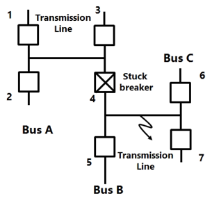
Sign in to UnlockConsider the protection system shown in the figure below. The circuit breakers, numbered from 1 to 7 are of identical type. A single line 10 ground fault with zero fault impedance occurs at the midpoint of the line (at point F), but circuit breaker 4 fails to operate ("stuck breaker"). If the relays are coordinated correctly, a valid sequence of circuit breaker operations is
Explanation Locked!
Unlock this branch to view the explanation, track, bookmark and more.
Sign in to UnlockKeeping in view the cost and overall effectiveness, the following circuit breaker is best suited for capacitor bank switching.
Explanation Locked!
Unlock this branch to view the explanation, track, bookmark and more.
Sign in to UnlockIn a biased differential relay, the bias is defined as a ratio of
Explanation Locked!
Unlock this branch to view the explanation, track, bookmark and more.
Sign in to UnlockThe transmission line distance protection relay having the property of being inherently directional is
Explanation Locked!
Unlock this branch to view the explanation, track, bookmark and more.
Sign in to UnlockThe interrupting time of a circuit breaker is the period between the instant of
Explanation Locked!
Unlock this branch to view the explanation, track, bookmark and more.
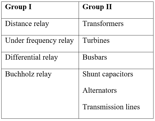
Sign in to UnlockA list of relays and the power system components protected by the relays are given in Group I and Group II respectively. Choose the correct match from the four choices given below:
Explanation Locked!
Unlock this branch to view the explanation, track, bookmark and more.
Sign in to UnlockConsider the problem of relay co-ordination for the distance relays R1 and R2 on adjacent lines of a transmission system (Figure). The Zone 1 and Zone 2 settings for both the relays are indicated on the diagram. Which of the following indicates the correct time setting for the Zone 2 of relays R1 and R2
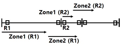


Explanation Locked!
Unlock this branch to view the explanation, track, bookmark and more.
Sign in to UnlockIn the protection of transformers, harmonic restrain is used to guard against
Explanation Locked!
Unlock this branch to view the explanation, track, bookmark and more.
Sign in to UnlockIn an inverse definite minimum time, electromagnetic type over-current relay the minimum time feature is achieved because of
Explanation Locked!
Unlock this branch to view the explanation, track, bookmark and more.
Sign in to UnlockIn a 3-step distance protection, the reach of the three zones of the relay at the beginning of the first line typically extends up to
Explanation Locked!
Unlock this branch to view the explanation, track, bookmark and more.
Sign in to UnlockThe plug setting of a negative sequence relay is 0.2A. The current transformer ratio is 5:1. The minimum value of line-to-line fault current for the operation of the relay is
1A

1.732A

Explanation Locked!
Unlock this branch to view the explanation, track, bookmark and more.
Sign in to UnlockThree sections of a feeder are provided with circuit breakers CB1, CB2, CB3, CB4, CB5 and CB6. For a fault F as indicated in fig.

Explanation Locked!
Unlock this branch to view the explanation, track, bookmark and more.
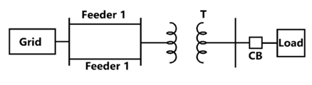
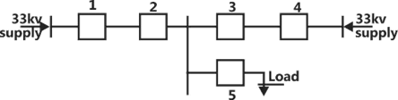
Sign in to UnlockDetermine the required MVA rating of the circuit breaker CB for the system shown in fig. Consider the grid as infinite bus. Choose 6 MVA as base.
Transformer: 3-phase, 33/11 kV, 6 MVA, 0.01+j0.08p.u. Impedance
Load: 3-phase, 11 kV, 5800 MVA, 0.8 lag, j0.2p.u. Impedance
Impedance of each feeder 9+j18 Ω
Explanation Locked!
Unlock this branch to view the explanation, track, bookmark and more.
Sign in to UnlockThe neutral of 10MVA, 11KV alternator is earthed through a resistance of 5 ohms. The earth fault relay is set to operate at 0.75A. The CT’s have a ratio of 1000:5.
What percentage of the alternator winding is protected?
Explanation Locked!
Unlock this branch to view the explanation, track, bookmark and more.
Sign in to UnlockReactance relay is normally preferred for protection against
Explanation Locked!
Unlock this branch to view the explanation, track, bookmark and more.
Sign in to UnlockResistance switching is normally employed in
Explanation Locked!
Unlock this branch to view the explanation, track, bookmark and more.
Sign in to UnlockIf the fault current is 2000A, the relay setting is 50% and CT ratio is 400:5, the plug setting multiplier will be
Explanation Locked!
Unlock this branch to view the explanation, track, bookmark and more.
Sign in to UnlockIf the inductance and capacitance of a power system network upto a circuit breaker location are 1H and 0.01μF respectively, the value of the shunt resistor across the circuit breaker, required for critical damping of the re-striking voltage is _________________
Explanation Locked!
Unlock this branch to view the explanation, track, bookmark and more.
Sign in to UnlockThe distance relay with inherent directional property is known as ________________ relay.
Explanation Locked!
Unlock this branch to view the explanation, track, bookmark and more.
Sign in to UnlockMatch the following
Explanation Locked!
Unlock this branch to view the explanation, track, bookmark and more.
Sign in to UnlockA three-phase delta-wye connected 30MVA, 33 kV/11 kV transformers is protected by a simple differential relaying scheme. The CT ratio on the primary side is 500: 5 and that on the secondary side is 2000: 5. Sketch the CT connection diagram for the relaying scheme. Also calculate the relay current setting for faults drawing upto 200% of the rated current.
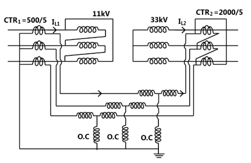
3.636
4.532
Explanation Locked!
Unlock this branch to view the explanation, track, bookmark and more.
Sign in to UnlockThe distribution system shown in figure is to be protected by over current system of protection.
For proper fault discrimination directional over current relays will be required at locations
Explanation Locked!
Unlock this branch to view the explanation, track, bookmark and more.
Sign in to UnlockA Buchholz relay is used for
Explanation Locked!
Unlock this branch to view the explanation, track, bookmark and more.
Sign in to UnlockMatch the following
Explanation Locked!
Unlock this branch to view the explanation, track, bookmark and more.
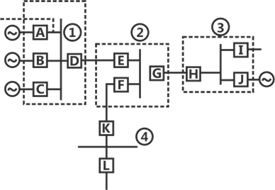
Sign in to UnlockIn a 4 bus system the circuit breakers and the various zones of protection are shown in figure. If the circuit breakers E, F and G trip, the location of the fault is on ___________
Explanation Locked!
Unlock this branch to view the explanation, track, bookmark and more.
Sign in to UnlockA 50 MVA, 132/66 kV, , three phase power transformer is protected by percentage differential relays. If the current transformers (CTs) located on the delta and wye sides of the power transformer are 300/5A and 1200/5A respectively.

Explanation Locked!
Unlock this branch to view the explanation, track, bookmark and more.
Sign in to Unlock