Power Systems
Power System Stability
Swing Equation
Questions mapped to Swing Equation under Power System Stability.
21
Total0
Attempted0
Correct0
IncorrectA 20 MVA, 11.2 kV, 4-pole, 50 Hz alternator has an inertia constant of 15 MJ /MVA. If the input and output powers of the alternator are 15 MW and 10 MW, respectively, the angular acceleration in mechanical degree/s² is ………………….. (round oft to nearest integer).
Sign in to see the solution
Log in to view the explanation, track your attempts, and keep your progress.
Sign in to UnlockThe figure shows the single line diagram of a power system with a double circuit transmission line. The expression for electrical power is 1.5 sin , where is the rotor angle. The system is operating at the stable equilibrium point with mechanical power equal to 1 pu. If one of the transmission line circuits is removed, the maximum value of , as the rotor swings, is 1.221 radian. If the expression for electrical power with one transmission line circuit removed is , the value of , in pu is ____________. (Give the answer up to three decimal places)




Sign in to see the solution
Log in to view the explanation, track your attempts, and keep your progress.
Sign in to UnlockA 3-phase, 2-pole, 50 Hz, synchronous generator has a rating of 250 MVA. 0.8 pf lagging. The kinetic energy of the machine at synchronous speed is 1000 MJ. The machine is running steadily at synchronous speed and delivering 60 MW power at a power angle of 10 electrical degrees. If the load is suddenly removed, assuming the acceleration is constant for 10 cycles, the value of the power angle after 5 cycles is ___________ electrical degrees.
Sign in to see the solution
Log in to view the explanation, track your attempts, and keep your progress.
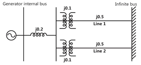
Sign in to UnlockThe single line diagram of a balanced power system is shown in the figure, The voltage magnitude at the generator internal bus is constant 1.0pu magnitude. The p.u. reactance’s of different components in the system are also shown in the figure. The infinite bus voltage magnitude is 1.0p.u. A three phase fault occurs at the middle of line 2. The ratio of the maximum real power that can be transferred during the pre-fault condition to the maximum real power that can be transferred under the faulted condition is_______________.
Sign in to see the solution
Log in to view the explanation, track your attempts, and keep your progress.
Sign in to UnlockA 50 Hz generating unit has H-constant of 2 MJ/MVA. The machine is initially operating in steady state at synchronous speed, and producing 1 pu of real power. The initial value of the rotor angle is 5º, when a bolted there phase to ground short circuit fault occurs terminal of the generator. Assuming the input mechanical power to remain at 1 pu, the value of in degrees, 0.02 second after the fault is ____________.
Sign in to see the solution
Log in to view the explanation, track your attempts, and keep your progress.
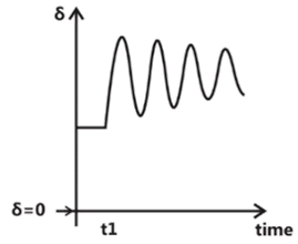
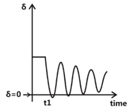
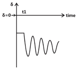
Sign in to UnlockThe synchronous generator shown in the figure is supplying active power to an infinite bus via two short, lossless transmission lines, and is initially in steady state. The mechanical power input to the generator and the voltage magnitude E are constant. If one line is tripped at time by opening the circuit breakers at the two ends (although there is no fault), then it is seen that the generator undergoes a stable transient. Which one of the following waveforms of the rotor angle shows the transient correctly?


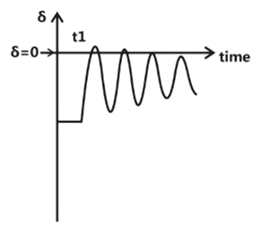
Sign in to see the solution
Log in to view the explanation, track your attempts, and keep your progress.
Sign in to UnlockThe figure shows the single line diagram of the single machine infinite bus system.

The inertia constant of the synchronous generator . Frequency is 50Hz. Mechanical power is 1pu. The system is operating at the stable equilibrium point with rotor angle equal to . A three phase short circuit fault occurs at a certain location on one of the circuits of the double circuit transmission line. During fault, electrical power in pu is . If the values of and at the instant of fault clearing are and 3.762 radian/s respectively, then (in pu) is _________.




Sign in to see the solution
Log in to view the explanation, track your attempts, and keep your progress.
Sign in to UnlockThe angle δ in the swing equation of a synchronous generator is the
Sign in to see the solution
Log in to view the explanation, track your attempts, and keep your progress.
Sign in to UnlockA cylindrical rotor generator delivers 0.5pu power in the steady state to an infinite bus through a transmission line of reactance 0.5pu. The generator no-load voltage is 1.5pu and the infinite bus voltage is 1pu. The inertia constant of the generator is 5 MW-s/MVA and the generator reactance is 1pu. The critical clearing angle, in degrees, for a three-phase dead short circuit fault at the generator terminal is
Sign in to see the solution
Log in to view the explanation, track your attempts, and keep your progress.
Sign in to UnlockA 500 MW, 21 kV, 50 Hz, 3-phase, 2-pole synchronous generator having a rated p.f = 0.9, has a moment of inertia of . The inertia constant (H) will be

Sign in to see the solution
Log in to view the explanation, track your attempts, and keep your progress.
Sign in to UnlockConsider a synchronous generator connected to an infinite bus by two identical parallel transmission lines. The transient reactance x' of the generator is 0.1pu and the mechanical power input to it is constant at 1.0pu. Due to some previous disturbance, the rotor angle (δ) is undergoing an un-damped oscillation, with the maximum value of equal to . One of the parallel lines trips due to relay mal-operation at an instant when · as shown in the figure. The maximum value of the per unit line reactance, x, such that the system does not lose synchronism subsequent to this tripping is



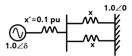
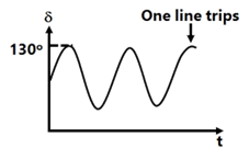
Sign in to see the solution
Log in to view the explanation, track your attempts, and keep your progress.
Sign in to UnlockA 50 Hz, 4-pole, 500 MVA, 22 kV turbo-generator is delivering rated megavolt amperes at 0.8 power factor. Suddenly a fault occurs reducing is electric power output by 40%. Neglect losses and assume constant power input to the shaft. The accelerating torque in the generator in MNm at the time of the fault will be
Sign in to see the solution
Log in to view the explanation, track your attempts, and keep your progress.
Sign in to UnlockA round rotor generator with internal voltage and X = 1.1 p.u. is connected to a round rotor synchronous motor with internal voltage and X = 1.2 p.u. The reactance of the line connecting the generator to the motor is 0.5 p.u. when the generator supplies 0.5 p.u. power, the rotor angle difference between the machines will be


Sign in to see the solution
Log in to view the explanation, track your attempts, and keep your progress.
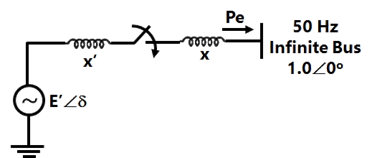
Sign in to UnlockA synchronous generator is to be connected to an infinite bus through a transmission line of reactance X = 0.2pu, as shown in Figure, the generator data is as follows:
x’ = 0.1pu, E’=1.0pu, H = 5MJ/MVA, mechanical power rad/sec.

All quantities are expressed on a common base.
The generator is initially running on open circuit with the frequency of the open circuit voltage slightly higher than that of the infinite bus. If at the instant of switch closure δ = 0 and , compute the maximum value of so that the generator pulls into synchronism.


Hint: Use the equation

Sign in to see the solution
Log in to view the explanation, track your attempts, and keep your progress.
Sign in to UnlockA power station consists of two synchronous generators A and B of ratings 250MVA and 500MVA with inertia 1.6p.u. and 1p.u., respectively on their own base MVA ratings. The equivalent p.u. inertia constant for the system on 100MVA common base is:
Sign in to see the solution
Log in to view the explanation, track your attempts, and keep your progress.
Sign in to UnlockA 100MVA, 11kV, 3-phase, 50Hz, 8-pole synchronous generator has an inertia constant H equal to 4 seconds. The stored energy in the rotor of the generator at synchronous speed will be

Sign in to see the solution
Log in to view the explanation, track your attempts, and keep your progress.
Sign in to UnlockThe use of high-speed circuit breakers
Sign in to see the solution
Log in to view the explanation, track your attempts, and keep your progress.
Sign in to UnlockA synchronous motor is receiving 50% of the power. It is capable of receiving from an infinite bus. If the load on the motor is suddenly reduced to 80% of the previous value, swing of the motor around its new equilibrium position.
Sign in to see the solution
Log in to view the explanation, track your attempts, and keep your progress.
Sign in to UnlockDuring a disturbance on a synchronous machine, the rotor swings from A to B before finally settling down to a steady state at point C on the power angle curve. The speed of the machine during oscillation is synchronous at point(s)
Sign in to see the solution
Log in to view the explanation, track your attempts, and keep your progress.
Sign in to UnlockIn a system, there are two generators operating in parallel. One generator, of rating 250 MVA, has an inertia-constant of 6 MJ/MVA while the other generator of 150 MVA has an inertia-constant of 4 MJ/MVA. The inertia-constant for the combined system on 100 MVA common base is ________________ MJ/MVA.
Sign in to see the solution
Log in to view the explanation, track your attempts, and keep your progress.
Sign in to UnlockThe transient stability of the power system can be effectively improved by
Sign in to see the solution
Log in to view the explanation, track your attempts, and keep your progress.
Sign in to Unlock