Network Analysis
Transient Analysis
Initial and Final Conditions
Questions mapped to Initial and Final Conditions under Transient Analysis.
12
Total0
Attempted0
Correct0
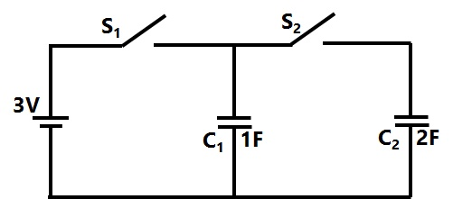
IncorrectIn the figure shown, all elements used are ideal. For time t < 0, \(S_1\) remained closed and \(S_2\) open. At
t = 0, \(S_1\) is opened and \(S_2\) is closed. If the voltage \(Vc_2\) across the capacitor \(C_2\) at t = 0 is zero, the voltage across the capacitor combination at will be

Sign in to see the solution
Log in to view the explanation, track your attempts, and keep your progress.
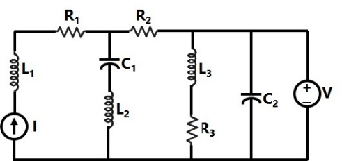
Sign in to UnlockIn the circuit shown in the figure, the current source I = 1A, voltage source V = 5V, , ,



In steady state, the currents (in A) through R3 and the voltage source V respectively will be
Sign in to see the solution
Log in to view the explanation, track your attempts, and keep your progress.
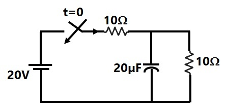
Sign in to UnlockIn Figure, the initial capacitor voltage is zero. The switch is closed at t = 0. The final steady-state voltage across the capacitor is:
Sign in to see the solution
Log in to view the explanation, track your attempts, and keep your progress.
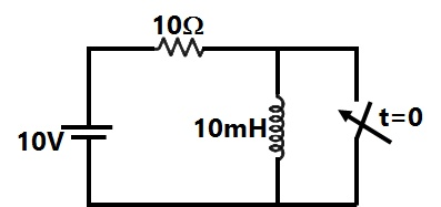
Sign in to UnlockThe circuit shown in Figure is in steady state, when the switch is closed at t = 0. Assuming that the inductance is ideal, the current through the inductor at equals
Sign in to see the solution
Log in to view the explanation, track your attempts, and keep your progress.
Sign in to UnlockA coil of inductance 10H resistance is connected as shown in figure. After the switch S has been in connected with point 1 for a very long time, it is moved to point 2 at t=0

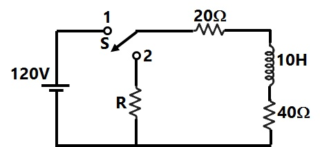
If, at t = 0+, the voltage across the coil is 120V, the value of resistance R is:
Sign in to see the solution
Log in to view the explanation, track your attempts, and keep your progress.
Sign in to UnlockThe RMS value of the resultant current in a wire which carries a dc current of 10 A and a sinusoidal alternating current of peak value 20 A is
Sign in to see the solution
Log in to view the explanation, track your attempts, and keep your progress.
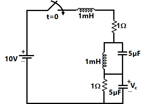
Sign in to UnlockIn the circuit shown in Figure, the switch is closed at time t = 0. The steady state value of the voltage is

Sign in to see the solution
Log in to view the explanation, track your attempts, and keep your progress.
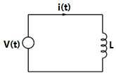
Sign in to UnlockIn the circuit shown in figure, it is desired to have a constant direct current i(t) through the ideal inductor L. the nature of the voltage source v(t) must be:
Sign in to see the solution
Log in to view the explanation, track your attempts, and keep your progress.
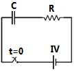
Sign in to UnlockIn the series RC circuit shown in figure the voltage across C starts increasing when the d.c. source is switched on. The rate of increase of voltage across C at the instant just after the switch is closed
(i.e., at ), will be

Sign in to see the solution
Log in to view the explanation, track your attempts, and keep your progress.
Sign in to UnlockThe time constant of the network shown in figure, is
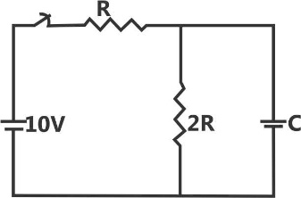
2RC
3RC


Sign in to see the solution
Log in to view the explanation, track your attempts, and keep your progress.
Sign in to UnlockTwo coils having equal resistance but different inductances are connected in series.
The time-constant of the series combination is:
Sign in to see the solution
Log in to view the explanation, track your attempts, and keep your progress.
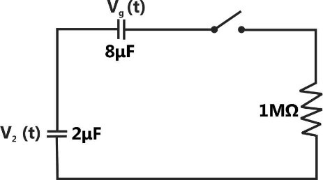
Sign in to UnlockThe switch S in figure is closed at t=0. If and respectively, voltages across the capacitors in steady state will be :






Sign in to see the solution
Log in to view the explanation, track your attempts, and keep your progress.
Sign in to Unlock