Power Systems
Transmission and Distribution
Power and ABCD Parameters
Questions mapped to Power and ABCD Parameters under Transmission and Distribution.
24
Total0
Attempted0
Correct0
IncorrectFor the balanced 3-phase transmission line shown, consider the following cases:
Case-1: p.u., p.u., p.u. and




Case-2: p.u., p.u., p.u. and


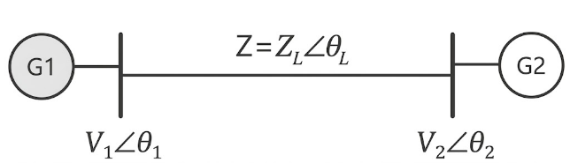
Which of the following statements is/are correct about real power loss and reactive power loss in the line?
Sign in to see the solution
Log in to view the explanation, track your attempts, and keep your progress.
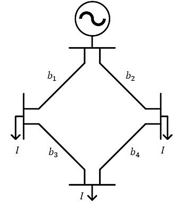
Sign in to UnlockThe figure shows the single line diagram of a 4-bus power network. Branches , , and have impedances , and per-unit (pu), respectively, where , with and . The current drawn from each load bus (marked as arrows) is equal to pu, where . If the network is to operate with minimum loss, the branch that should be opened is












Sign in to see the solution
Log in to view the explanation, track your attempts, and keep your progress.
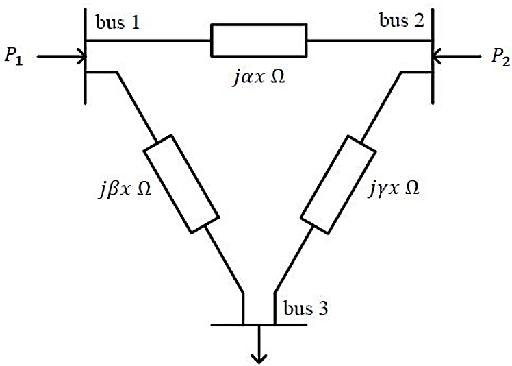
Sign in to UnlockFor the three-bus lossless power network shown in the figure, the voltage magnitudes at all the buses are equal to 1 per unit , and the differences of the voltage phase angles are very small. The line reactances are marked in the figure, where , and are strictly positive. The bus injections and are in pu. If , where , and the real power flow from bus 1 to bus 2 is , then which one of the following options is correct?












Sign in to see the solution
Log in to view the explanation, track your attempts, and keep your progress.
Sign in to UnlockAn alternator with internal voltage of . and synchronous reactance of 0.4 p.u is connected by a transmission line of reactance 0.1 p.u. to a synchronous motor having synchronous reactance 0.35 pu. and internal voltage of If the real power supplied by the altemator is 0.866 p.u, then is …………… degrees. (Round off to 2 decimal places) (Machines are of non-salient type. Neglect resistances)



Sign in to see the solution
Log in to view the explanation, track your attempts, and keep your progress.
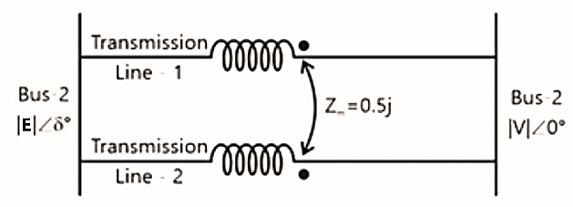
Sign in to UnlockIn the figure shown, self-impedances of the two transmission Iines are 1.5j p.u each, and is the mutual impedance. Bus voltages shown in the figure are in p.u. Given that , the maximum steady-state real power that can be transferred in p.u from Bus-1 to Bus-2 is






Sign in to see the solution
Log in to view the explanation, track your attempts, and keep your progress.
Sign in to UnlockBus 1 with voltage magnitude is sending reactive power towards bus 2 with voltage magnitude through a lossless transmission line of reactance X. Keeping the voltage at bus 2 fixed at 1 pu, magnitude of voltage at bus 1 is changed, so that the reactive power sent from bus 1 is increased by



20%. Real power flow through the line under both the conditions is zero. The new value of the voltage magnitude, , in pu (rounded off to 2 decimal places), at bus 1 is __________.


Sign in to see the solution
Log in to view the explanation, track your attempts, and keep your progress.
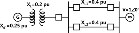
Sign in to UnlockIn the single machine infinite bus system shown below, the generator is delivering the real power of 0.8 pu at 0.8 power factor lagging to the infinite bus. The power angle of the generator in degrees (round off to one decimal place) is _________.
Sign in to see the solution
Log in to view the explanation, track your attempts, and keep your progress.
Sign in to UnlockConsider a lossy transmission line with and as the sending and receiving end voltages, respectively. Z and X are the series impedance and reactance of the line, respectively. The steady-state stability limit for the transmission line will be

Greater than

Less than
equal to
equal to
Sign in to see the solution
Log in to view the explanation, track your attempts, and keep your progress.
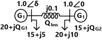
Sign in to UnlockConsider the two bus power system network with given loads as shown in the figure. All the values shown in the figure are in per unit. The reactive power supplied by generator and are and respectively. The per unit values of and line reactive power loss respectively are






Sign in to see the solution
Log in to view the explanation, track your attempts, and keep your progress.
Sign in to UnlockA two bus power system shown in the figure supplies load of 1.0 + j0.5 p.u
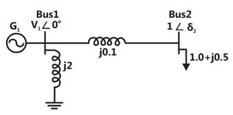
The values of in p.u. and respectively are

0.95 and

1.05 and

1.1 and

1.1 and

Sign in to see the solution
Log in to view the explanation, track your attempts, and keep your progress.
Sign in to UnlockA three phase star-connected load is drawing power at a voltage of 0.9 pu and 0.8 power factor lagging. The three phase base power and base current are 100 MVA and 437.38 A respectively. The line-to-line load voltage in kV is______________.
Sign in to see the solution
Log in to view the explanation, track your attempts, and keep your progress.
Sign in to UnlockConsider two buses connected by an impedance of. The bus 1 voltage is 10030°V, and bus 2 voltage is . The real and reactive power supplied by bus 1, respectively are







Sign in to see the solution
Log in to view the explanation, track your attempts, and keep your progress.
Sign in to UnlockFor a fixed value of complex power flow in a transmission line having a sending end voltage V, the real power loss will be proportional to
V



Sign in to see the solution
Log in to view the explanation, track your attempts, and keep your progress.
Sign in to UnlockConsider the two power systems shown in figure A below, which are initially not interconnected, and are operating in steady state at the same frequency. Separate load flow solutions are computed individually for the two systems, corresponding to this scenario. The bus voltage phasors so obtained are indicated on figure A. These two isolated systems are now interconnected by a short transmission line as shown in figure B, and it is found that.

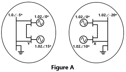
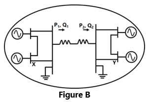
The bus voltage phase angular difference between generator bus X and generator bus Y after the interconnection is




Sign in to see the solution
Log in to view the explanation, track your attempts, and keep your progress.
Sign in to UnlockThe A, B, C, D constants of a 220 kV line are: , , . If the sending end voltage of the line for a given load delivered at nominal voltage is 240 kV, then % voltage regulation of the line is



Sign in to see the solution
Log in to view the explanation, track your attempts, and keep your progress.
Sign in to UnlockThe generalized circuit constants of a 3-phase, 220 kV rated voltage, medium length transmission line are



If the load at the receiving end is 50 MW at 220 kV with a power factor of 0.9 lagging, the magnitude of line to line sending end voltage should be
Sign in to see the solution
Log in to view the explanation, track your attempts, and keep your progress.
Sign in to UnlockThe ABCD parameters of a 3-phase overhead transmission line are , and . At no-load condition a shunt inductive reactor is connected at the receiving end of the line to limit the receiving end voltage to be equal to the sending end voltage. The ohmic value of the reactor is







Sign in to see the solution
Log in to view the explanation, track your attempts, and keep your progress.
Sign in to UnlockA 3-phase, 11-kV generator feeds power to a constant power unity power factor load of 100 MW through a 3-phase transmission line. The line-to-line voltage at the terminals of the machine is maintained constant at 11 kV. The per unit positive sequence impedance of the line based on 100 MVA and 11 kV is j 0.2. The line-to-line voltage at the load terminals is measured to be less than 11 kV. The total reactive power to be injected at the terminals of the load to increase the line-to-line voltage at the load terminals to 11 kV is
Sign in to see the solution
Log in to view the explanation, track your attempts, and keep your progress.
Sign in to UnlockA 50 Hz balanced three-phase, Y-connected supply is connected to a balanced three phase Y-connected load. If the instantaneous phase-α of the supply voltage is and the phase-α of the load current is , the instantaneous three-phase power is


A constant with a magnitude of

A constant with a magnitude of

Time-varying with an average value of and a frequency of 100Hz
Time-varying with an average value of and a frequency of 50 Hz

Sign in to see the solution
Log in to view the explanation, track your attempts, and keep your progress.
Sign in to UnlockA 220kV, 20 km long , 3-phase transmission line has the following A, B, C, D constants. , ,




11A
220A

Sign in to see the solution
Log in to view the explanation, track your attempts, and keep your progress.
Sign in to UnlockThe per unit voltages of two synchronous machines connected through a lossless line are. Match the two sides in the following

(a) Real power of machine 1 | (P) Positive real power |
(b) Reactive power of machine 1 | (Q) Positive reactive power |
(c) Power factor of machine 1 | (R) Negative real power |
(S) Negative reactive power | |
(T) Leading power factor | |
(U) Lagging power factor |
Sign in to see the solution
Log in to view the explanation, track your attempts, and keep your progress.
Sign in to UnlockTwo identical three-phase transmission lines are connected in parallel to supply a total load of 100 MW at 132 kV and 0.8p.f lagging at the receiving end. The ABCD constants of each transmission line are as follows:
;


Determine:
(a) The ABCD constants of the combined network.
(b) The sending-end power factor
(a)
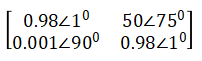
(b) 0.729
(a)
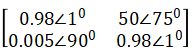
(b) 0.829
(a)
(b) 0.629
(a)
(b) 0.729
Sign in to see the solution
Log in to view the explanation, track your attempts, and keep your progress.
Sign in to UnlockWhen a fixed amount of power is to be transmitted, the efficiency of transmission increases when
Sign in to see the solution
Log in to view the explanation, track your attempts, and keep your progress.
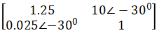
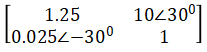
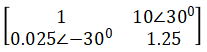
Sign in to UnlockTwo transmission lines are connected in cascade, whose ABCD parameters are

Respectively. Find the resultant ABCD parameters.
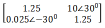
Sign in to see the solution
Log in to view the explanation, track your attempts, and keep your progress.
Sign in to Unlock