Power Systems
Transmission and Distribution
Power Factor Correction
Questions mapped to Power Factor Correction under Transmission and Distribution.
14
Total0
Attempted0
Correct0
IncorrectUsing shunt capacitors, the power factor of a 3 -phase, 4 kV induction motor (drawing 390 kVA at 0.77 pf lag) is to be corrected to 0.85 pf lag. The line current of the capacitor bank, in A, is _________ (round off to one decimal place).
Sign in to see the solution
Log in to view the explanation, track your attempts, and keep your progress.
Sign in to UnlockA load is supplied by a 230 V, 50 Hz source. The active power P and the reactive power Q consumed by the load are such that .and A capacitor connected across the load for power factor correction generates 1 kVAR reactive power. The worst case power factor after power factor correction is


Sign in to see the solution
Log in to view the explanation, track your attempts, and keep your progress.
Sign in to UnlockA three-phase cable is supplying 800kW and 600 kVAr to an inductive load. It is intended to supply an additional resistive load of 100kW through the same cable without increasing the heat dissipation in the cable, by providing a three-phase bank of capacitors connected in star across the load. Given the line voltage is 3.3kV, 50Hz, the capacitance per phase of the bank, expressed in microfarads, is _______________.
Sign in to see the solution
Log in to view the explanation, track your attempts, and keep your progress.
Sign in to UnlockThe power consumption of an industry is 500 kVA, at 0.8 p.f. lagging. A synchronous motor is added to raise the power factor of the industry to unity. If the power intake of the motor is 100 kW, the p.f. of the motor is_______________.
Sign in to see the solution
Log in to view the explanation, track your attempts, and keep your progress.
Sign in to UnlockA single phase induction motor draws 12 MW power at 0.6 lagging power. A capacitor is connected in parallel to the motor to improve the power factor of the combination of motor and capacitor to 0.8 lagging. Assuming that the real and reactive power drawn by the motor remains same as before, the reactive power delivered by the capacitor in MVAR is ______________.
Sign in to see the solution
Log in to view the explanation, track your attempts, and keep your progress.
Sign in to UnlockThe complex power consumed by a constant-voltage load is given by , where and .A compensating shunt capacitor is chosen such that , where Q is the net reactive power consumed by the capacitor-load combination. The reactive power (in kVAR) supplied by the capacitor is ____________.




Sign in to see the solution
Log in to view the explanation, track your attempts, and keep your progress.
Sign in to UnlockFor the system shown below, and are complex power demands at bus 1 and bus 2 respectively. If , the VAR rating of the capacitor connected at bus 2 is




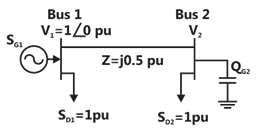
Sign in to see the solution
Log in to view the explanation, track your attempts, and keep your progress.
Sign in to UnlockMatch the items in List-I with the items in List-II and select the correct answer using the codes given below the lists.
List I | List II |
To | Use |
a. Improve power factor | 1. shunt reactor |
b. Reduce the current ripples | 2. shunt capacitor |
c. Increase the power flow in line | 3. series capacitor |
d. Reduce the Ferranti effect | 4. series reactor |
Sign in to see the solution
Log in to view the explanation, track your attempts, and keep your progress.
Sign in to UnlockA 400V, 50 Hz, three phase balanced source supplies power to a star connected load whose rating is kVA, 0.8 pf (lag). The rating (in kVAR) of the delta connected (capacitive) reactive power bank necessary to bring the pf to unity is

Sign in to see the solution
Log in to view the explanation, track your attempts, and keep your progress.
Sign in to UnlockAt an industrial sub-station with a 4 MW load, a capacitor of 2 MVAR is installed to maintain the load power factor at 0.97 lagging. If the capacitor goes out of service, the load power factor becomes
Sign in to see the solution
Log in to view the explanation, track your attempts, and keep your progress.
Sign in to UnlockA balanced delta connected load of (8+j6) Ω per phase is connected to a 400 V, 50 Hz, 3-phase supply lines. If the input power factor is to be improved to 0.9 by connecting a bank of star connected capacitors the required kVAR of the bank
Sign in to see the solution
Log in to view the explanation, track your attempts, and keep your progress.
Sign in to UnlockA 3-phase, 11kV, 50 Hz, 200 kW load has a power factor of 0.8lag. A delta connected 3-phase capacitor is used to improve the power factor to unity. The capacitance power phase of the capacitor in microfarads is
Sign in to see the solution
Log in to view the explanation, track your attempts, and keep your progress.
Sign in to UnlockA circuit consisting of a single resistor R and an inductor L in series is driven by a 25V RMS, 50 Hz sinusoidal voltage source. A capacitor is to be placed in parallel with the source to improve the power factor. Given that the average power dissipated in the R is 100W and that the reactive power delivered to the L is 75VAR, what value of C will yield a 0.9 p.f. lagging as seen by the source?
Sign in to see the solution
Log in to view the explanation, track your attempts, and keep your progress.
Sign in to UnlockA factory draws 100kW at 0.7p.f lagging from a 3-phase, 11 kV supply. It is desired to raise the p.f. to 0.95 lagging using series capacitors. Calculate the rating of the capacitor required in μF .
Sign in to see the solution
Log in to view the explanation, track your attempts, and keep your progress.
Sign in to Unlock