Power Systems
Load Flow Analysis
Power System Matrices
Questions mapped to Power System Matrices under Load Flow Analysis.
29
Total0
Attempted0
Correct0
IncorrectConsider a power system with buses, of which are generator buses and the remaining are load buses (where there is no generation).



Assume that there are no reactive power-limit violations at the generator buses.
What is the size of the Jacobian matrix in the Newton-Raphson load flow method?




Sign in to see the solution
Log in to view the explanation, track your attempts, and keep your progress.
Sign in to UnlockA three-phase two-winding transformer has a voltage transformation ratio , where is the primary side voltage in p.u., and is the secondary side voltage in p.u. and represent the currents injected into the primary and secondary sides of the transformer, respectively. The admittance corresponding to the leakage impedance of the transformer referred to the secondary is p.u. Neglect the magnetizing branch.






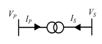
The Y bus representation of this transformer is:




Sign in to see the solution
Log in to view the explanation, track your attempts, and keep your progress.
Sign in to UnlockThe bus admittance matrix of a 3-bus power system is given below.

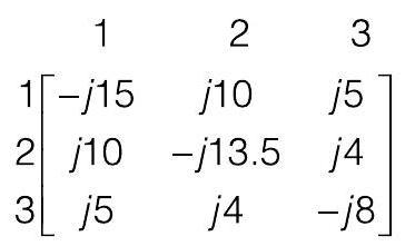
Considering that there is no shunt inductor connected to any of the buses, which of the following can NOT be true?
Sign in to see the solution
Log in to view the explanation, track your attempts, and keep your progress.
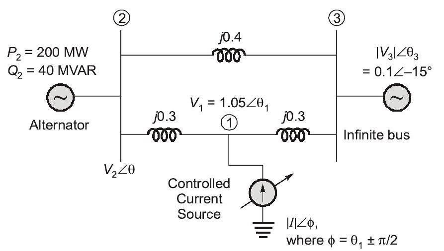
Sign in to UnlockThe three-bus power system shown in the figure has one alternator connected to bus 2 which supplies 200 MW and 40 MVAr power. Bus 3 is infinite bus having a voltage of magnitude p.u. and angle of . A variable current source, is connected at bus 1 and controlled such that the magnitude of the bus 1 voltage is maintained at



1.05 p.u. and the phase angle of the source current, , where is the phase angle of the bus 1 voltage. The three buses can be categorized for load flow analysis as


Bus 1 Slack Bus
Bus Bus

Bus Bus

Bus Bus

Bus Bus

Bus Bus

Bus 3 Slack Bus
Bus Bus

Bus Bus
Bus 3 Slack Bus
Bus Bus

Bus 3 Slack Bus
Sign in to see the solution
Log in to view the explanation, track your attempts, and keep your progress.
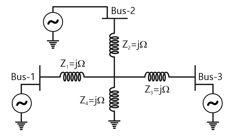
Sign in to UnlockA 3-Bus network is shown. Consider generators as ideal voltage sources. If rows 1, 2 and 3 of the matrix correspond to Bus 1, 2 and 3 respectively, then of the network is





Sign in to see the solution
Log in to view the explanation, track your attempts, and keep your progress.
Sign in to UnlockTwo buses, i and j, are connected with a transmission line of admittance Y, at the two ends of which there are ideal transformers with turns ratios as shown. Bus admittance matrix for the system is:
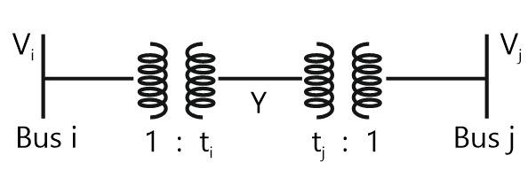




Sign in to see the solution
Log in to view the explanation, track your attempts, and keep your progress.
Sign in to UnlockThe matrix of a two-bus power system having two identical parallel lines connected between them in pu is given as


The magnitude of the series reactance of each line in pu (round off up to one decimal place) is ________________.
Sign in to see the solution
Log in to view the explanation, track your attempts, and keep your progress.
Sign in to UnlockA bus admittance matrix for an electric power system has 8000 non-zero elements. The minimum number of branches (transmission lines and transformers) in this system is _____ (up to 2 decimal places).

Sign in to see the solution
Log in to view the explanation, track your attempts, and keep your progress.
Sign in to UnlockThe figure shows the per-phase representation of a phase-shifting transformer connected between buses 1 and 2, where is a complex number with non-zero real and imaginary parts.

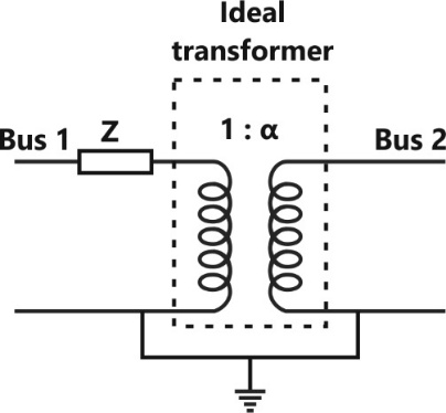
For the given circuit, and are bus admittance matrix and bus impedance matrix, respectively, each of size 2 × 2. Which one of the following statements is true?


Both and are symmetric
is symmetric and is unsymmetric
is unsymmetric and is symmetric
Both and are unsymmetric
Sign in to see the solution
Log in to view the explanation, track your attempts, and keep your progress.
Sign in to UnlockA 3-bus power system is shown in the figure below, where the diagonal elements of Y-bus matrix are:

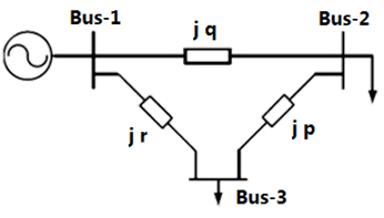
The per unit values of the line reactance’s p, q and shown in the figure are




Sign in to see the solution
Log in to view the explanation, track your attempts, and keep your progress.
Sign in to UnlockThe bus admittance matrix for a power system network is

There is a transmission line, connected between buses 1 and 3, which is represented by the circuit shown in figure.
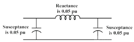
If this transmission line is removed from service, what is the modified bus admittance matrix?




Sign in to see the solution
Log in to view the explanation, track your attempts, and keep your progress.
Sign in to UnlockA 3-bus power system network consists of 3 transmission lines. The bus admittance matrix of the uncompensated system is

If the shunt capacitance of all transmission lines is 50% compensated, the imaginary part of the row column element (in pu) of the bus admittance matrix after compensation is

Sign in to see the solution
Log in to view the explanation, track your attempts, and keep your progress.
Sign in to UnlockFor a power system network with n nodes, of its bus impedance matrix is j0.5 per unit. The voltage at node 3 is per unit. If a capacitor having reactance of –j3.5 per unit is now added to the network between node 3 and the reference node, the current drawn by the capacitor per unit is


Sign in to see the solution
Log in to view the explanation, track your attempts, and keep your progress.
Sign in to UnlockIn the following network, the voltage magnitudes at all buses are equal to 1 p.u., the voltage phase angles are very small, and the line resistances are negligible. All the line reactances are equal to j1 Ω.
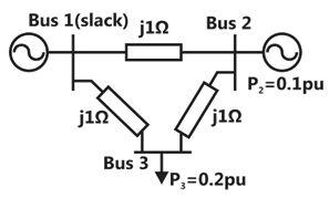
The voltage phase angles in rad at buses 2 and 3 are




Sign in to see the solution
Log in to view the explanation, track your attempts, and keep your progress.
Sign in to UnlockIn the following network, the voltage magnitudes at all buses are equal to 1 p.u., the voltage phase angles are very small, and the line resistances are negligible. All the line reactances are equal to j1 Ω.
If the base impedance and the line-to-line base voltage are 100 Ω and 100kV, respectively, then the real power in MW delivered by the generator connected at the slack bus is
Sign in to see the solution
Log in to view the explanation, track your attempts, and keep your progress.
Sign in to UnlockThe bus admittance matrix of a three-bus three-line system is

If each transmission line between the two buses is represented by an equivalent -network, the magnitude of the shunt susceptance of the line connecting bus 1 and 2 is

Sign in to see the solution
Log in to view the explanation, track your attempts, and keep your progress.
Sign in to UnlockA three-bus network is shown in the figure below indicating the p.u. impedance of each element.
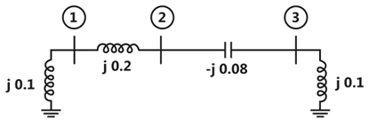
The Bus admittance matrix, Y-bus, of the network is




Sign in to see the solution
Log in to view the explanation, track your attempts, and keep your progress.
Sign in to UnlockFor the Y-bus matrix of a 4-bus system given in per unit, the buses having shunt elements are

Sign in to see the solution
Log in to view the explanation, track your attempts, and keep your progress.
Sign in to UnlockThe network shown in Figure has impedances in p.u. as indicated. The diagonal element of the bus admittance matrix YBUS of the network is:


Sign in to see the solution
Log in to view the explanation, track your attempts, and keep your progress.
Sign in to UnlockThe Z matrix of a 2-port network as given by

The element of the corresponding Y matrix of the same network is given by
Sign in to see the solution
Log in to view the explanation, track your attempts, and keep your progress.
Sign in to UnlockThe bus impedance matrix of a 4-bus power system is given by

A branch having an impedance of j0.2Ω is connected between bus 2 and the reference. Then the values of and of the bus impedance matrix of the modified network are respectively.


Sign in to see the solution
Log in to view the explanation, track your attempts, and keep your progress.
Sign in to UnlockA power system consists of 2 areas (Area 1 and Area 2) connected by a single tie line (Figure). It is required to carry out a load flow study on this system. While entering the network data, the tie-line data (connectivity and parameters) is inadvertently left out. If the load flow program is run with this incomplete data
Sign in to see the solution
Log in to view the explanation, track your attempts, and keep your progress.
Sign in to UnlockFor the Y-bus matrix given in per unit values, where the first, second, third and fourth row refers to bus 1, 2, 3 and 4 respectively, draw the reactance diagram.

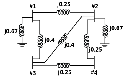
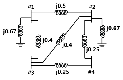
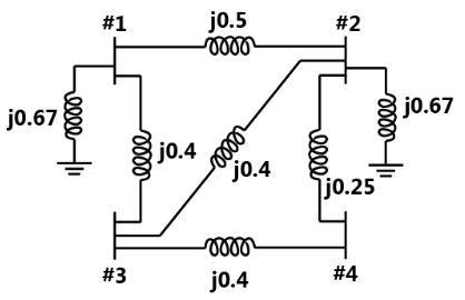
None
Sign in to see the solution
Log in to view the explanation, track your attempts, and keep your progress.
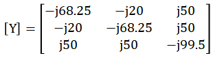
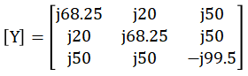
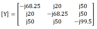
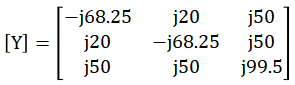
Sign in to UnlockFor the given network in fig., obtain the bus admittance matrix using the data given:

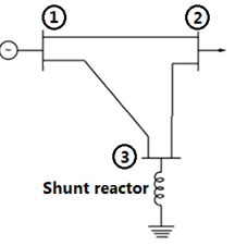
Line between nodes | Impedance p.u. | Half of line charging admittance |
1-2 | 0.0+j0.05 | j1.25 |
1-3 | 0.0+j0.02 | j0.50 |
2-3 | 0.0+j0.02 | j0.50 |
Shunt reactor at node 3 | Impedance |
0.0+j2.0 |
Sign in to see the solution
Log in to view the explanation, track your attempts, and keep your progress.
Sign in to UnlockIf the reference bus is changed in two load flow runs with same system data and power obtained for reference bus taken as specified P and Q in the latter run
Sign in to see the solution
Log in to view the explanation, track your attempts, and keep your progress.
Sign in to UnlockIn load-flow analysis, a voltage-controlled bus is treated as a load bus in subsequent iterations if a reactive power limit is violated. (True=1/False=0)
Sign in to see the solution
Log in to view the explanation, track your attempts, and keep your progress.
Sign in to UnlockIn load flow analysis, the load connected at a bus is represented as
Sign in to see the solution
Log in to view the explanation, track your attempts, and keep your progress.
Sign in to UnlockIn load flow studies of a power system, the quantities specified at a voltage-controlled bus are _______________ and _______________
Sign in to see the solution
Log in to view the explanation, track your attempts, and keep your progress.
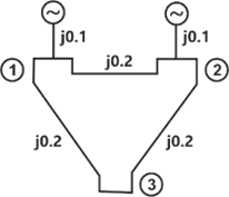
Sign in to UnlockA sample power system network is shown in figure. The reactance’s marked are in p.u. The p.u value of of the Bus Admittance Matrix is:
Sign in to see the solution
Log in to view the explanation, track your attempts, and keep your progress.
Sign in to Unlock