Digital Electronics
Sequential Circuits
Flip Flops
Questions mapped to Flip Flops under Sequential Circuits.
15
Total0
Attempted0
Correct0
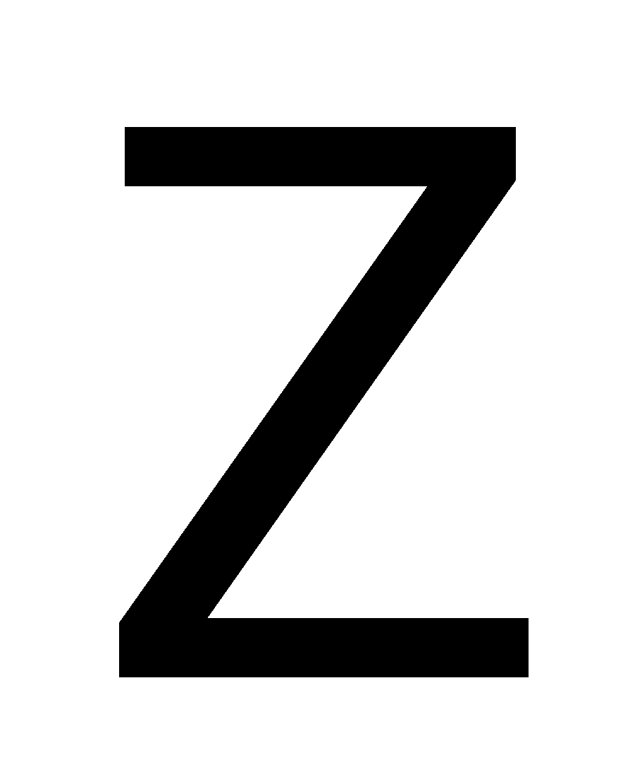
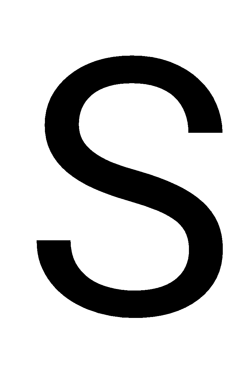
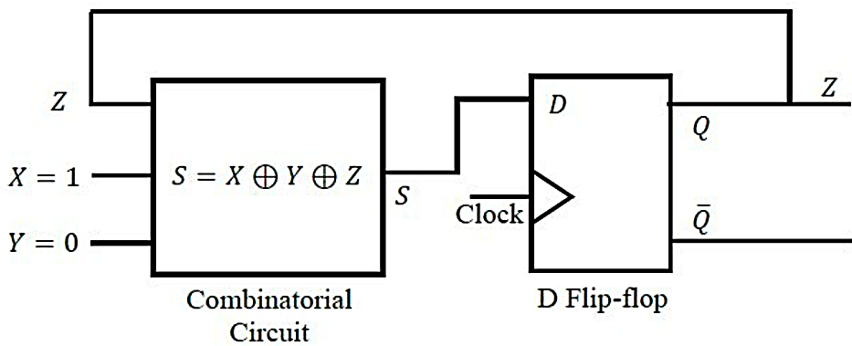
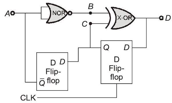
IncorrectIn the circuit, the present value of is 1. Neglecting the delay in the combinatorial circuit, the values of and , respectively, after the application of the clock will be
Sign in to see the solution
Log in to view the explanation, track your attempts, and keep your progress.
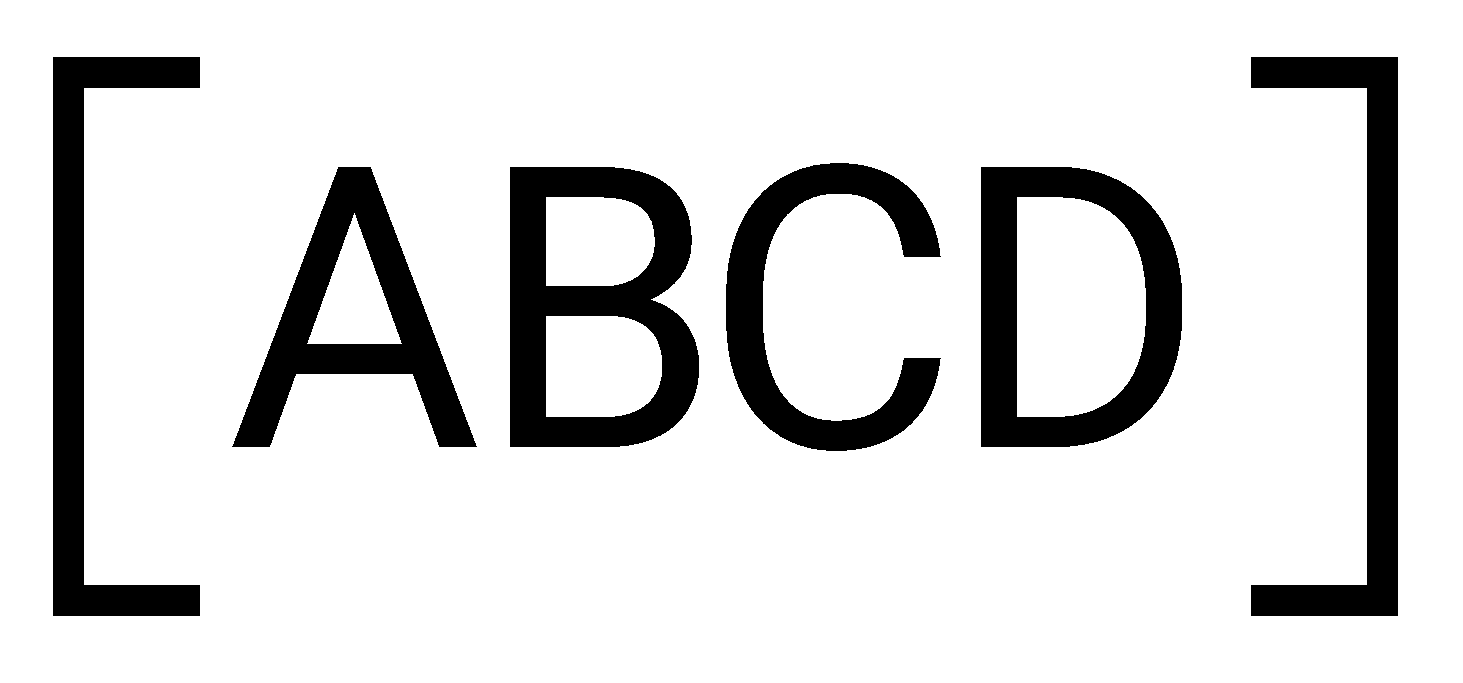
Sign in to UnlockNeglecting the delays due to the logic gates in the circuit shown in figure, the decimal equivalent of the binary sequence of initial logic states, which will not change with clock, is
Sign in to see the solution
Log in to view the explanation, track your attempts, and keep your progress.
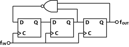
Sign in to UnlockWhich one of the following statements is true about the digital circuit shown in the figure?
Sign in to see the solution
Log in to view the explanation, track your attempts, and keep your progress.
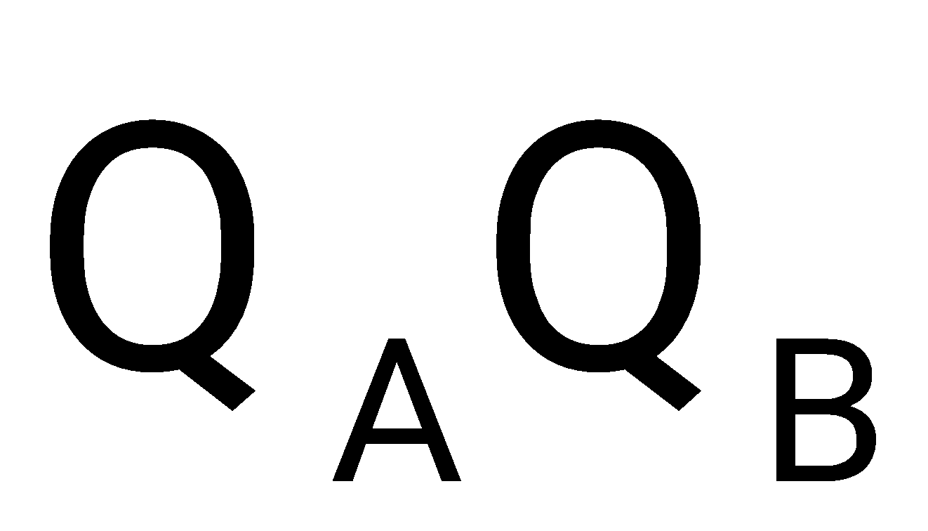
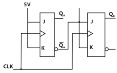
Sign in to UnlockThe current state of a two JK flip-flop system is 00. Assume that the clock rise-time is much smaller than the delay of the JK flip-flop. The next state of the system is
Sign in to see the solution
Log in to view the explanation, track your attempts, and keep your progress.
Sign in to UnlockA JK flip flop can be implemented by T flip-flops. Identify the correct implementation.
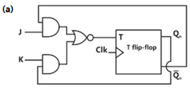
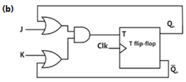
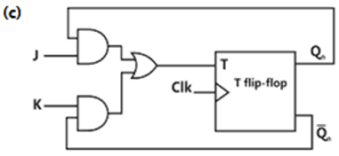

Sign in to see the solution
Log in to view the explanation, track your attempts, and keep your progress.
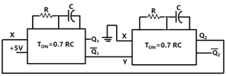
Sign in to UnlockTwo monoshot multivibrators, one positive edge triggered and another negative edge triggered are connected as shown in figure
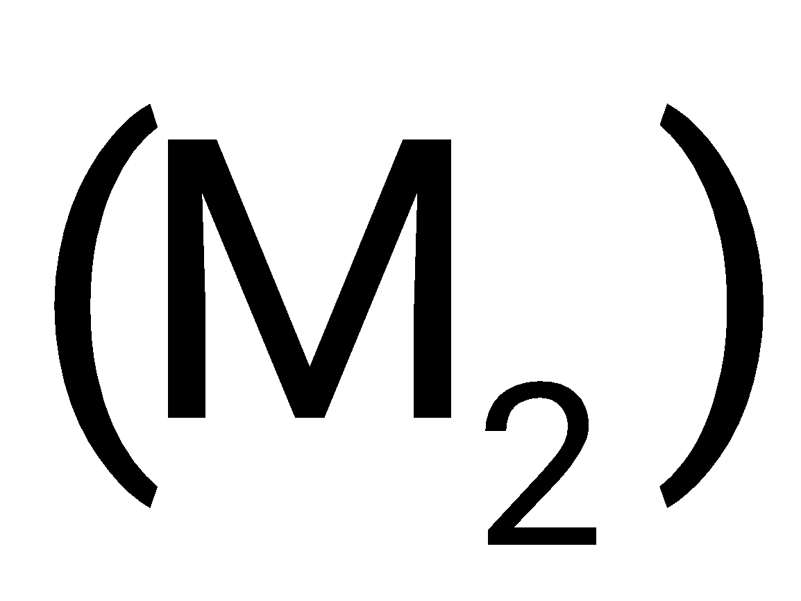
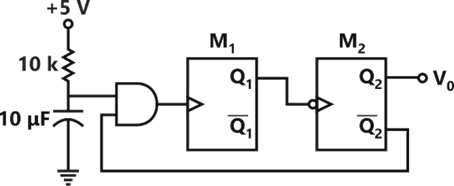
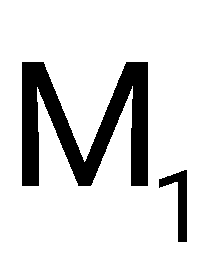
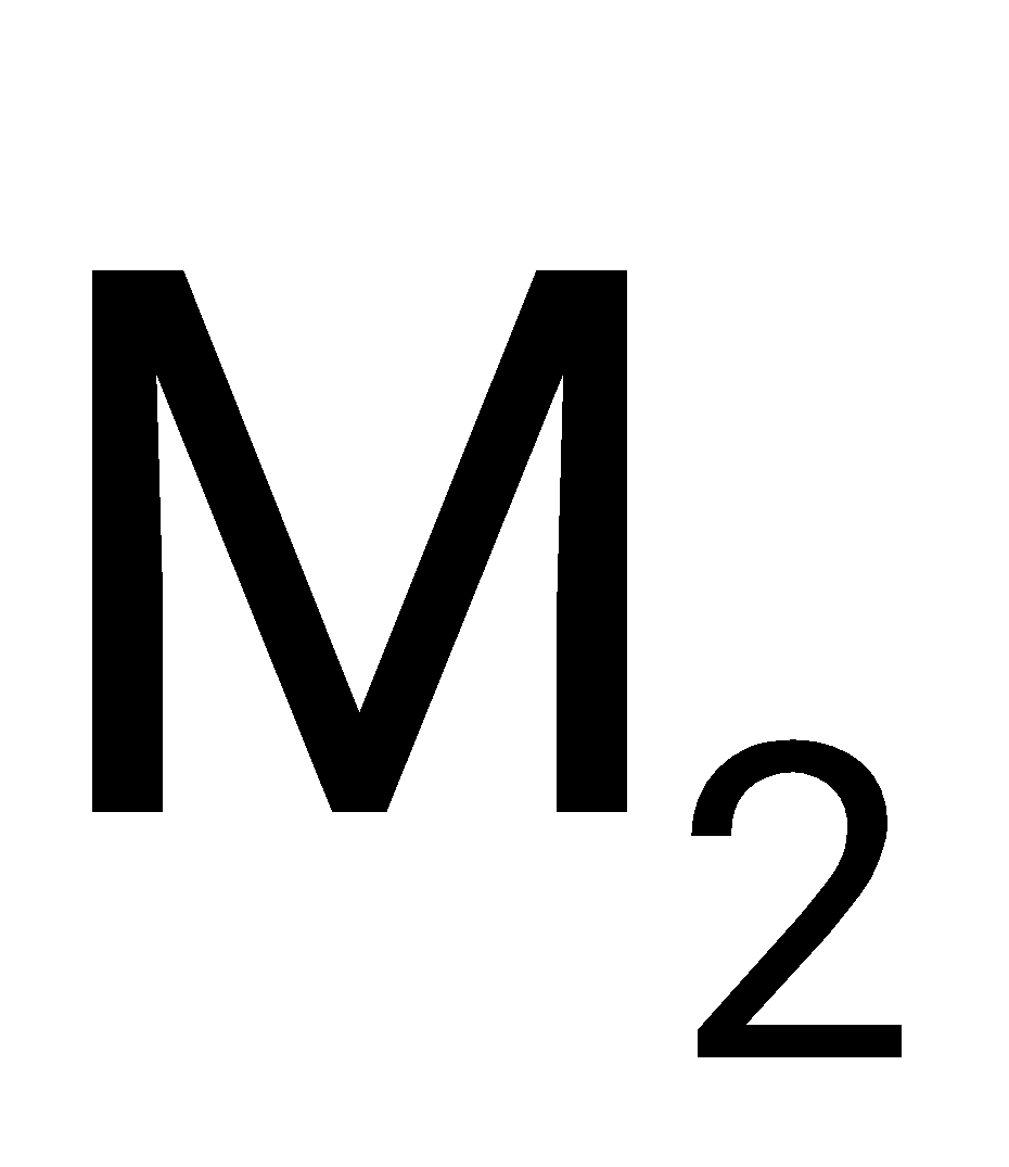
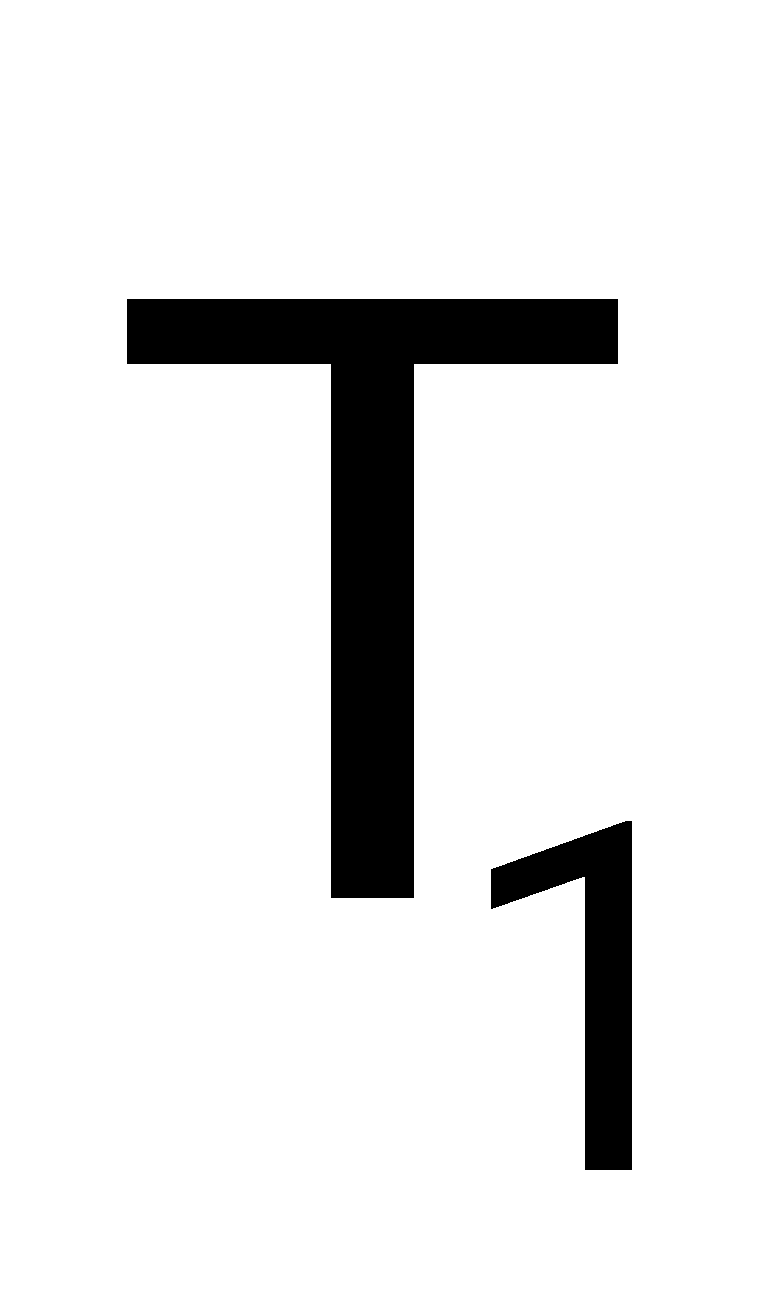
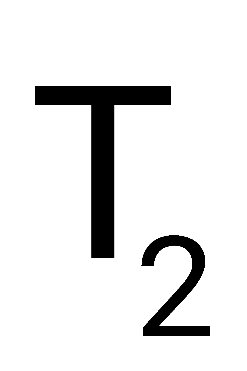
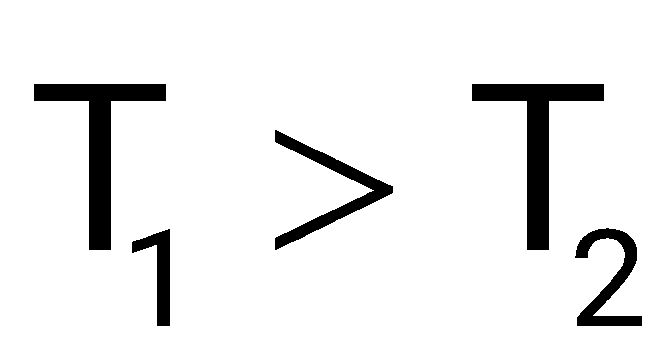
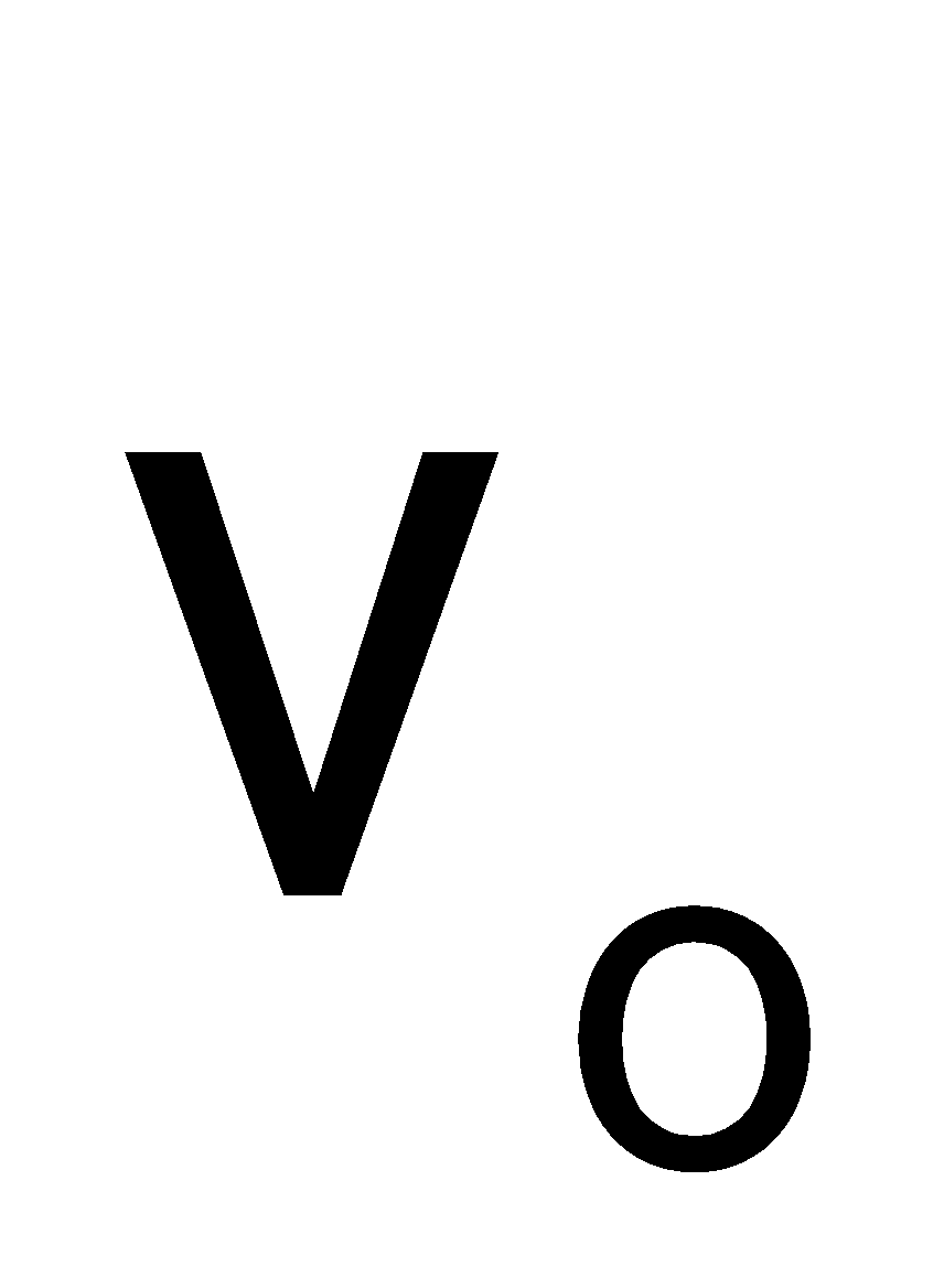
The monoshots and when triggered produce pulse of width and respectively. Where . The steady state output voltage of the circuit is
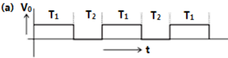
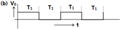
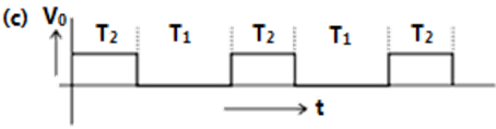
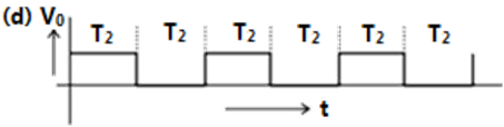
Sign in to see the solution
Log in to view the explanation, track your attempts, and keep your progress.
Sign in to UnlockConsider the given circuit,
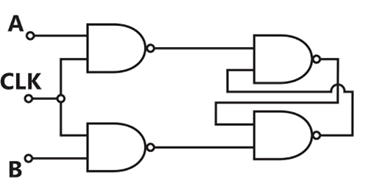
In this circuit, the race around
Sign in to see the solution
Log in to view the explanation, track your attempts, and keep your progress.
Sign in to UnlockThe truth table of a monoshot shown in the figure is given in the table below:
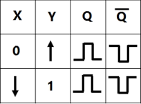
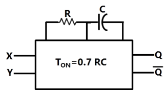
Two monoshots, one positive edge triggered and other negative edge triggered, are connected as shown in the figure. The pulse widths of the two monoshot outputs, , and , are and , respectively.
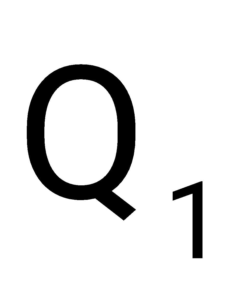
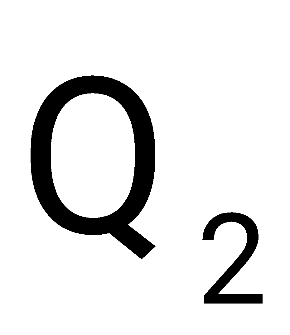
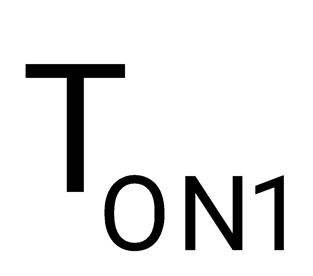
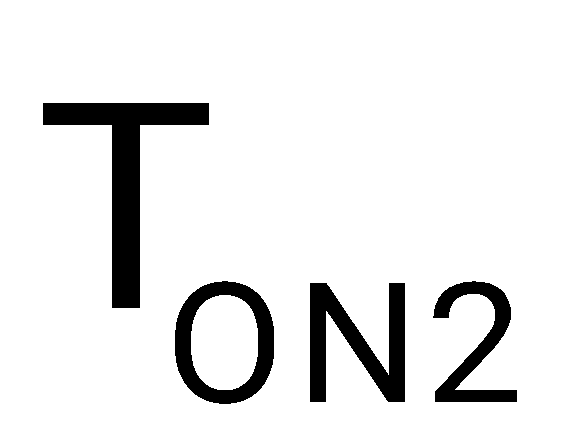
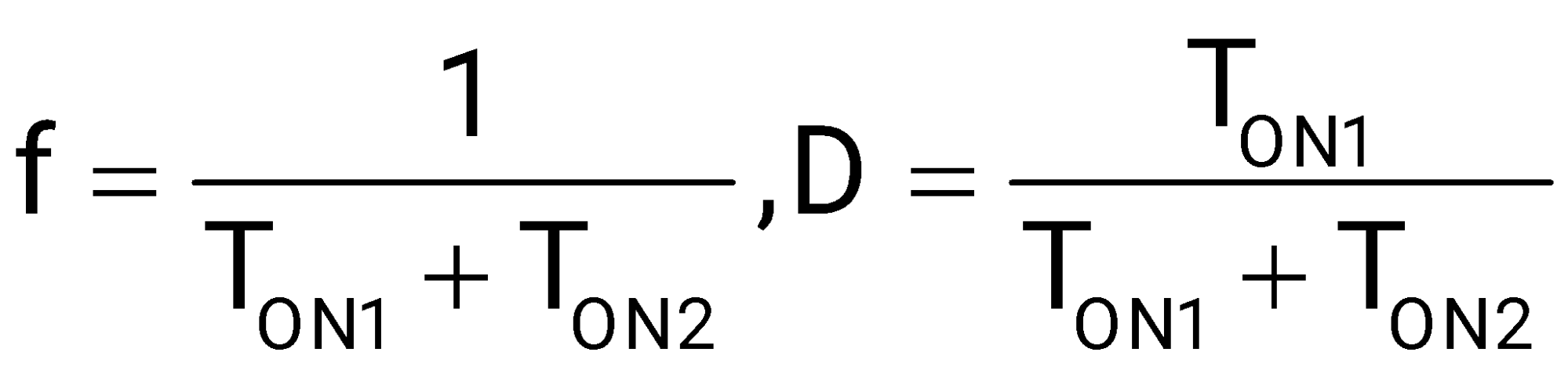
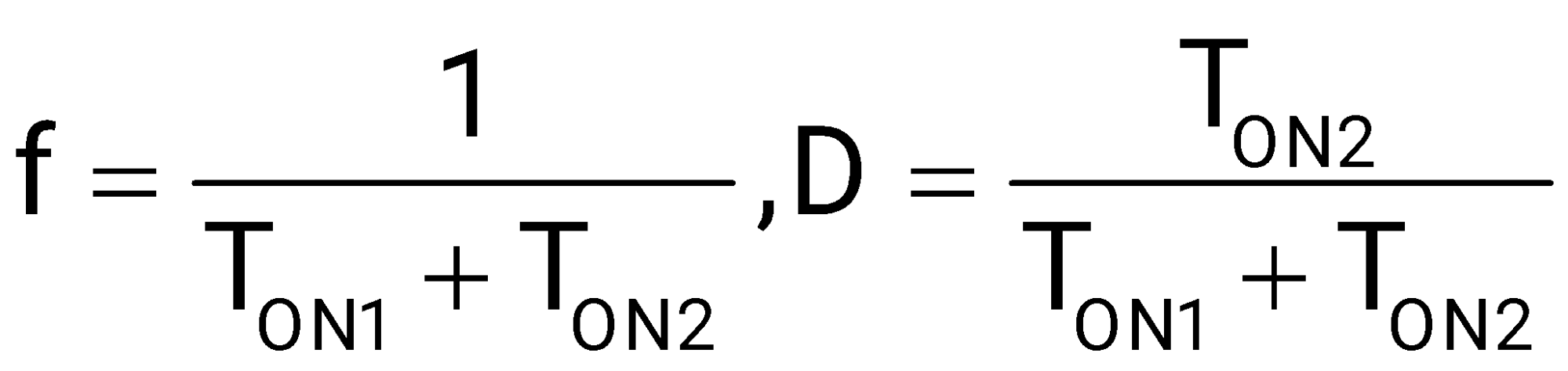
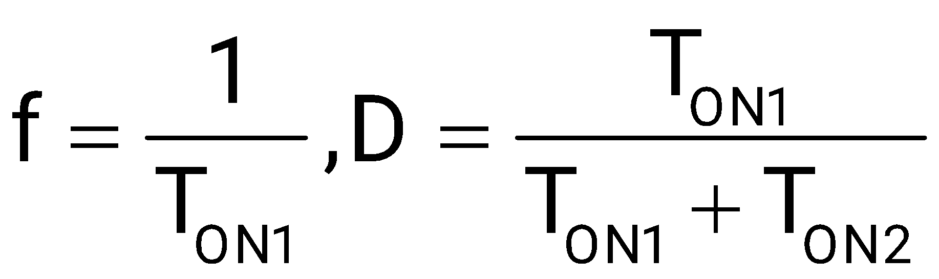
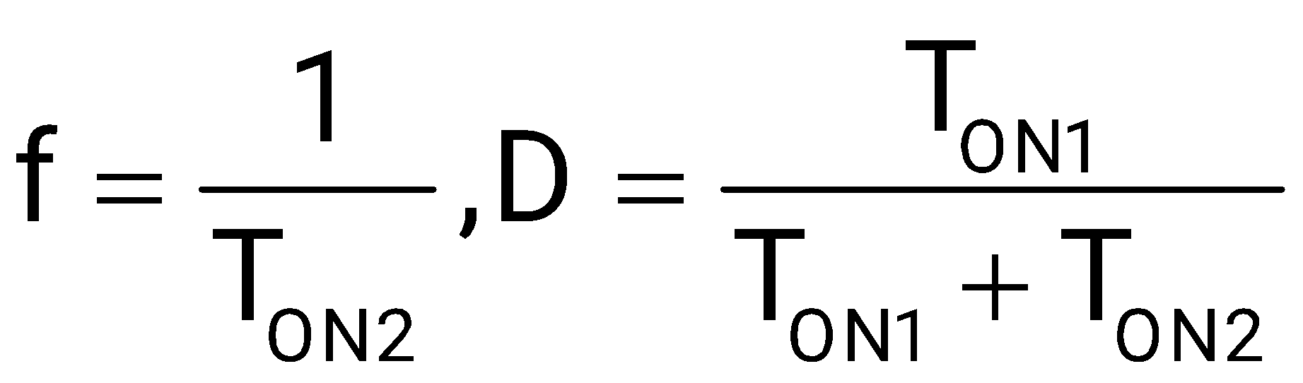
The frequency and the duty cycle of the signal at Q1 will respectively be
Sign in to see the solution
Log in to view the explanation, track your attempts, and keep your progress.
Sign in to UnlockSelect the circuit, which will produce the given output Q for the input signals X1 and X2 given in Figure.
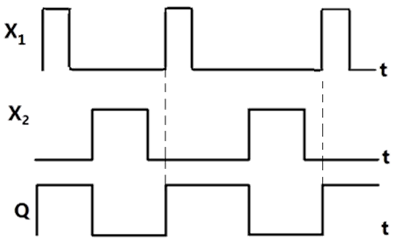
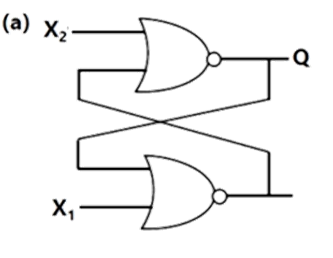

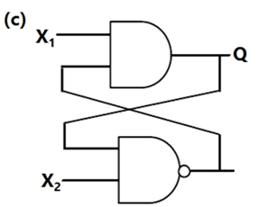
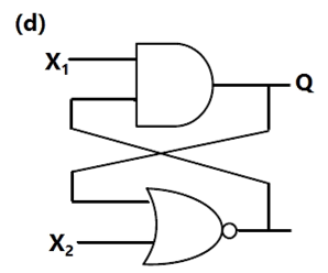
Sign in to see the solution
Log in to view the explanation, track your attempts, and keep your progress.
Sign in to UnlockIn figure, as long as and , the output Q remains
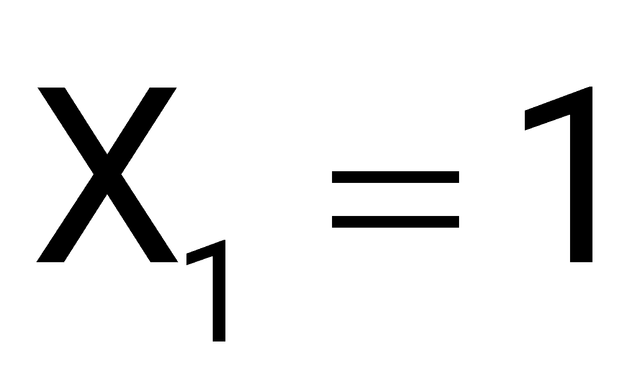
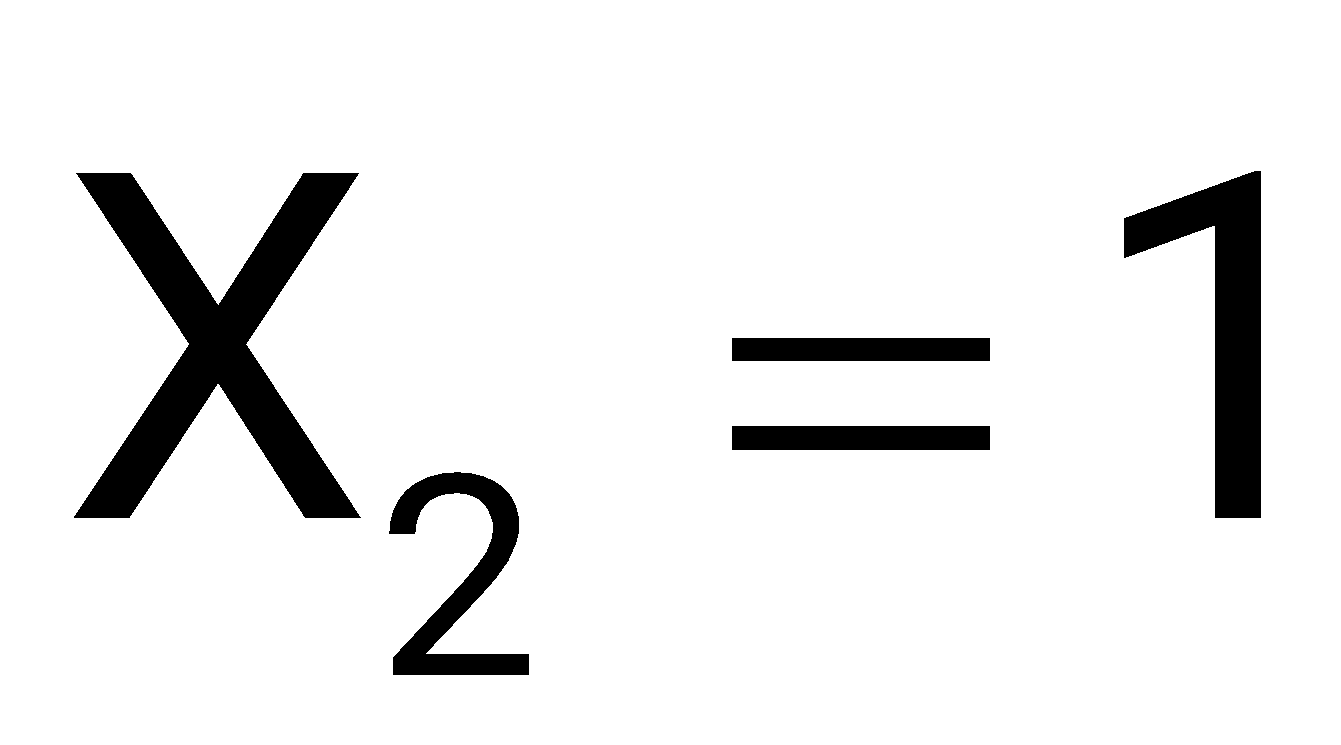
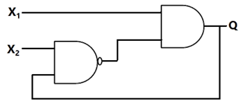
Sign in to see the solution
Log in to view the explanation, track your attempts, and keep your progress.
Sign in to UnlockThe digital circuit shown in figure generates a modified clock pulse at the output. Choose the correct output waveform form the options given below.

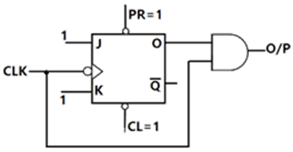
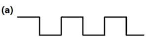
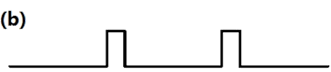
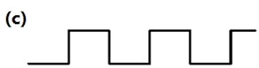
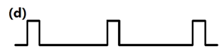
Sign in to see the solution
Log in to view the explanation, track your attempts, and keep your progress.
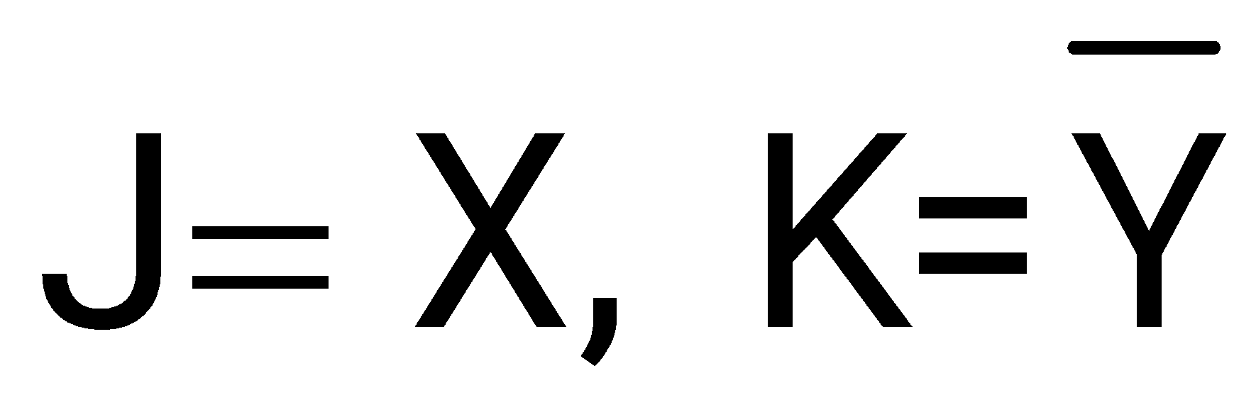
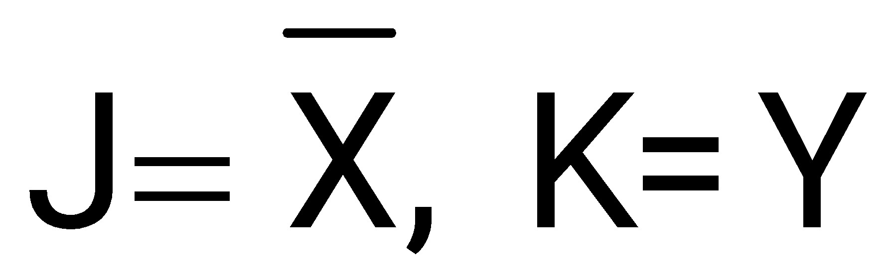
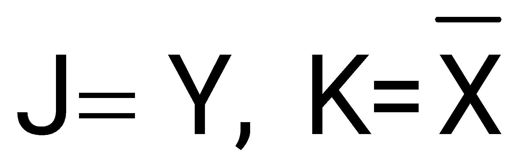
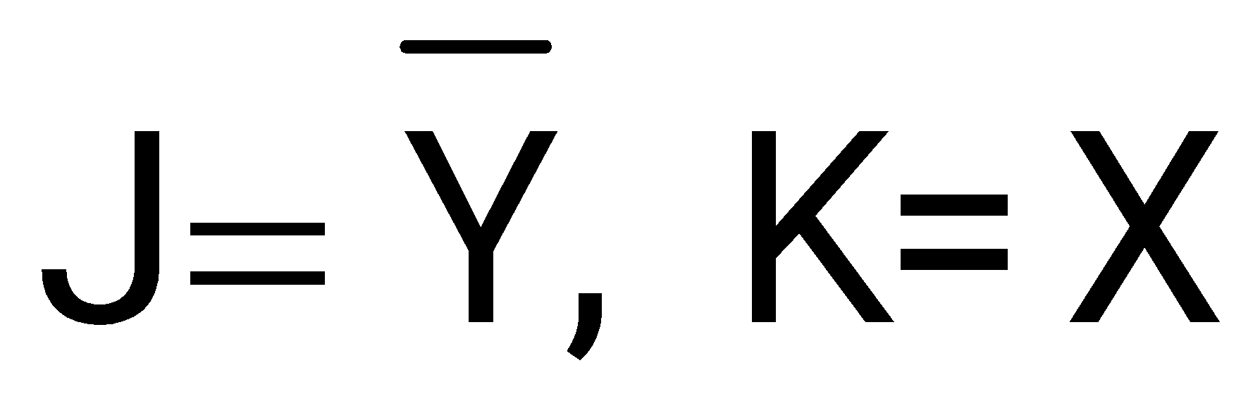
Sign in to UnlockAn X-Y flip flop, whose Characteristic Table is given below is to be implemented using a J-K flip flop
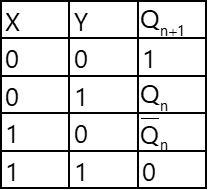
This can be done by making
Sign in to see the solution
Log in to view the explanation, track your attempts, and keep your progress.
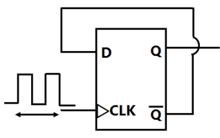
Sign in to UnlockThe frequency of the clock signal applied to the rising edge triggered D flip-flop shown in figure is 10 kHz. The frequency of the signal available at Q is
Sign in to see the solution
Log in to view the explanation, track your attempts, and keep your progress.
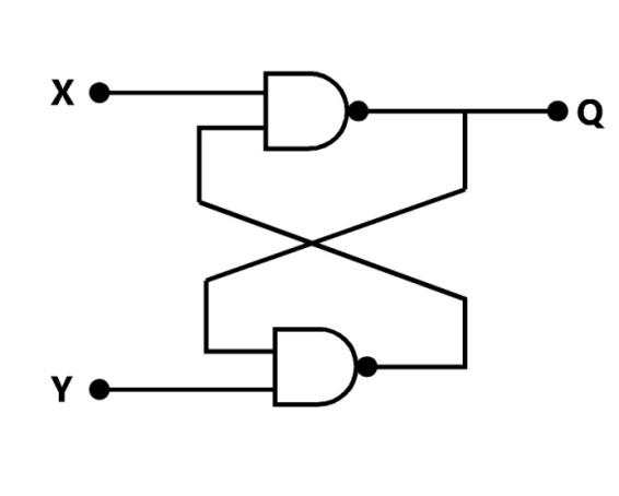
Sign in to UnlockFor a flip-flop formed from two NAND gates as shown, the unusable state corresponds to
Sign in to see the solution
Log in to view the explanation, track your attempts, and keep your progress.
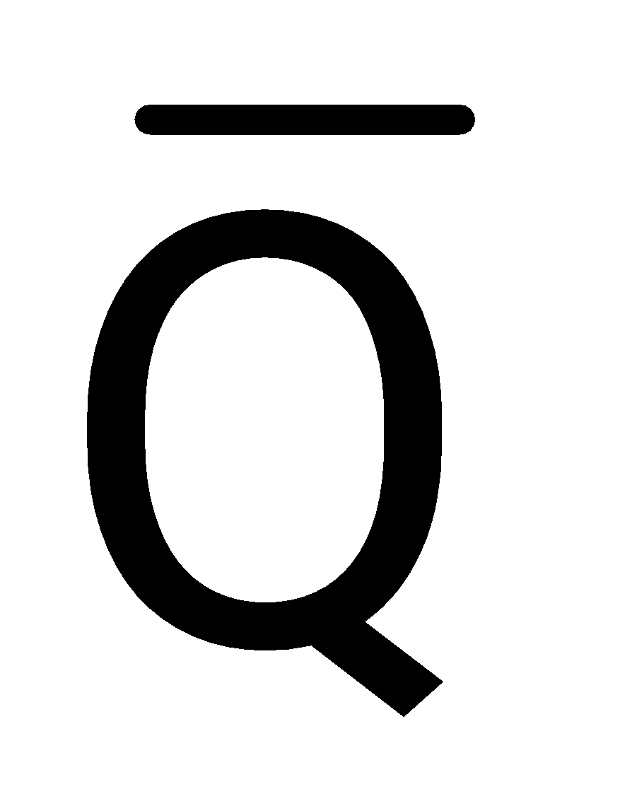
Sign in to UnlockFor a J-K flip-flop its J input is tied to its own output and its K input is connected to its own Q output. If the flip-flop is fed with a clock of frequency 1MHz, its Q output frequency will be _________________
Sign in to see the solution
Log in to view the explanation, track your attempts, and keep your progress.
Sign in to Unlock