Network Analysis
Sinusoidal Steady State Analysis
Phasor Analysis
Questions mapped to Phasor Analysis under Sinusoidal Steady State Analysis.
24
Total0
Attempted0
Correct0
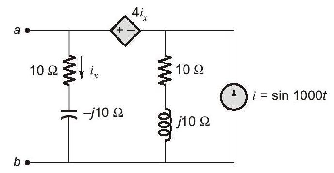
IncorrectFor the circuit shown, if , the instantaneous value of the Thevenin's equivalent voltage (in Volts) across the terminals at time is __________ (Round off to 2 decimal places).



Sign in to see the solution
Log in to view the explanation, track your attempts, and keep your progress.
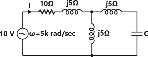
Sign in to UnlockIn the given circuit, the value of capacitor C that makes current I = 0 is _________ μF.
Sign in to see the solution
Log in to view the explanation, track your attempts, and keep your progress.
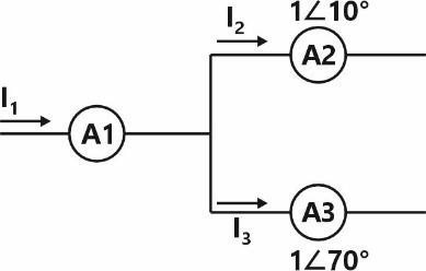
Sign in to UnlockCurrent through ammeters and in fig. are 1 ∠ 10° and 1 ∠ 70° respectively. The reading of the ammeter A1 (rounded off to 3 decimal places) is _________ A.


Sign in to see the solution
Log in to view the explanation, track your attempts, and keep your progress.
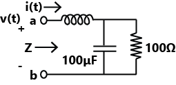
Sign in to UnlockThe voltage v(t) across the terminals a and b as shown in the figure, is a sinusoidal voltage having a frequency . When the inductor current i(t) is in phase with the voltage v(t), the magnitude of the impedance Z (in ) seen between the terminals a and is _______ (up to 2 decimal places).


Sign in to see the solution
Log in to view the explanation, track your attempts, and keep your progress.
Sign in to UnlockThe equivalent impedance for the infinite ladder circuit shown in the figure is

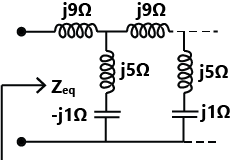




Sign in to see the solution
Log in to view the explanation, track your attempts, and keep your progress.
Sign in to UnlockIn the circuit shown below, the supply voltage is volts. The peak value of the steady state current through the resistor, in amperes, is _________________.


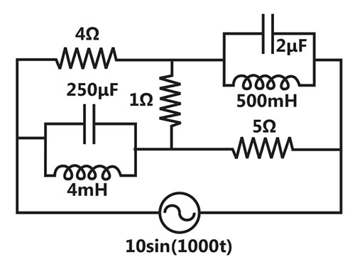
Sign in to see the solution
Log in to view the explanation, track your attempts, and keep your progress.
Sign in to UnlockA resistance and a coil connected in series and supplied from a phase, 100V, 50Hz ac source as shown in the figure below. The rms values of possible voltages across the resistance and coil respectively, in volts are


`
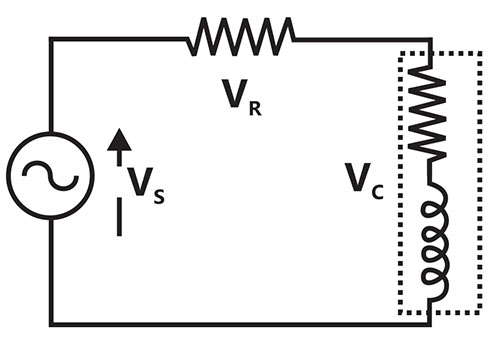
Sign in to see the solution
Log in to view the explanation, track your attempts, and keep your progress.
Sign in to UnlockThe circuit shown in the figure has two sources connected in series. The instantaneous voltage of the AC source (in Volt) is given by . If the circuit is in steady state, then the RMS value of the current (in Ampere) flowing in the circuit is

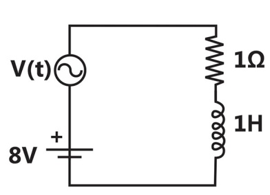
Sign in to see the solution
Log in to view the explanation, track your attempts, and keep your progress.
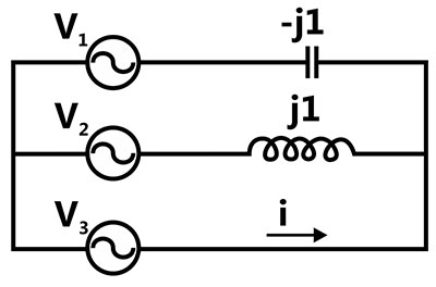
Sign in to UnlockIn the given network. , ,



The phasor current i (in Ampere) is




Sign in to see the solution
Log in to view the explanation, track your attempts, and keep your progress.
Sign in to UnlockThe voltage across the capacitor, as shown in the figure, is expressed as +


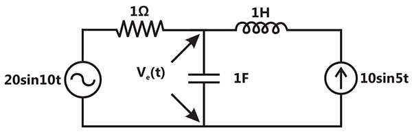
The values of and respectively, are


Sign in to see the solution
Log in to view the explanation, track your attempts, and keep your progress.
Sign in to UnlockIn the circuit shown below, the current through the inductor is
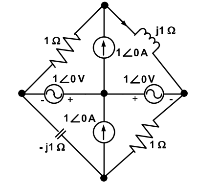



0 A
Sign in to see the solution
Log in to view the explanation, track your attempts, and keep your progress.
Sign in to UnlockThe RMS value of the current i(t) in the circuit shown below is
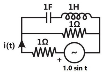


1A

Sign in to see the solution
Log in to view the explanation, track your attempts, and keep your progress.
Sign in to UnlockThe voltage applied to a circuit is volts and the circuit draws a current of amperes. Taking the voltage as the reference phasor, the phasor representation of the current in amperes is






Sign in to see the solution
Log in to view the explanation, track your attempts, and keep your progress.
Sign in to UnlockAn RLC circuit with relevant data is given below.
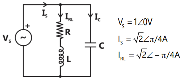
The current in the figure above is

–j 2A


+j2 A
Sign in to see the solution
Log in to view the explanation, track your attempts, and keep your progress.
Sign in to UnlockIn the figure given below all phasors are with reference to the potential at point "O". The locus of voltage phasor as R is varied from zero to infinity is shown by

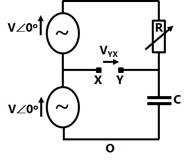
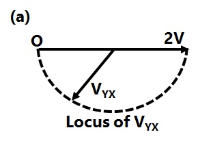
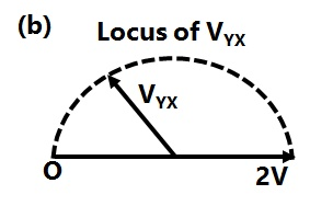
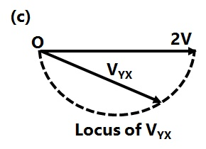
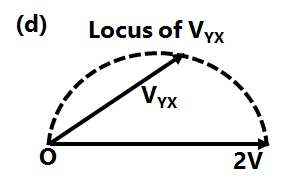
Sign in to see the solution
Log in to view the explanation, track your attempts, and keep your progress.
Sign in to UnlockThe RMS value of the voltage is:


5V
7V

Sign in to see the solution
Log in to view the explanation, track your attempts, and keep your progress.
Sign in to UnlockThe RL circuit of Figure is fed from a constant magnitude, variable frequency sinusoidal voltage source . At 100 Hz, the R and L elements each have a voltage drop . If the frequency of the source is changed to 50 Hz, the new voltage drop across R is:


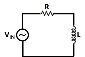




Sign in to see the solution
Log in to view the explanation, track your attempts, and keep your progress.
Sign in to UnlockIn figure, the admittance values of the elements in Siemens are
respectively.

The value of I as a phasor when the voltage E across the elements isis

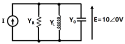
Sign in to see the solution
Log in to view the explanation, track your attempts, and keep your progress.
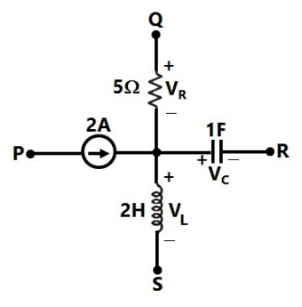
Sign in to UnlockA segment of a circuit is shown in Figure. , . The voltage is given by



Sign in to see the solution
Log in to view the explanation, track your attempts, and keep your progress.
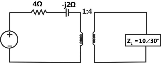
Sign in to UnlockThe impedance seen by the source in the circuit in figure, is given by




Sign in to see the solution
Log in to view the explanation, track your attempts, and keep your progress.
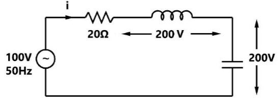
Sign in to UnlockThe current in the circuit shown in figure is:
Sign in to see the solution
Log in to view the explanation, track your attempts, and keep your progress.
Sign in to UnlockA fixed capacitor of reactance –j0.02 kΩ is connected in parallel across a series combination of a fixed inductor of reactance j0.01 kΩ and a variable resistance R. As R is varied from zero to infinity, the locus diagram of the admittance of this L-C-R circuit will be
Sign in to see the solution
Log in to view the explanation, track your attempts, and keep your progress.
Sign in to UnlockA sinusoidal source of voltage V and frequency f is connected to a series circuit of variable resistance, R and a fixed reactance, X. the locus of the tip of the current-phasor I, as R is varied from 0 to ∞ is:
A semicircle with a diameter of

A straight line with a slop of

An ellipse with as major axis

A circle of radius and origin at


Sign in to see the solution
Log in to view the explanation, track your attempts, and keep your progress.
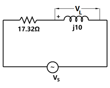
Sign in to UnlockIn the given circuit, the voltage , has a phase angle of _____________ with respect to .


Sign in to see the solution
Log in to view the explanation, track your attempts, and keep your progress.
Sign in to Unlock