Network Analysis
Sinusoidal Steady State Analysis
Resonance
Questions mapped to Resonance under Sinusoidal Steady State Analysis.
21
Total0
Attempted0
Correct0
IncorrectAn inductor having a 𝑄-factor of 60 is connected in series with a capacitor having a 𝑄-factor of 240. The overall 𝑄-factor of the circuit is ________. (round off to nearest integer)
Sign in to see the solution
Log in to view the explanation, track your attempts, and keep your progress.
Sign in to UnlockThe network shown below has a resonant frequency of 150 kHz and a bandwidth of 600 Hz. The 𝑄-factor of the network is __________. (round off to nearest integer)
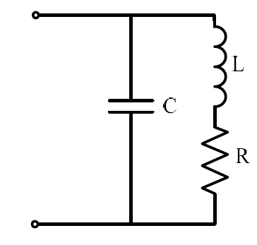
Sign in to see the solution
Log in to view the explanation, track your attempts, and keep your progress.
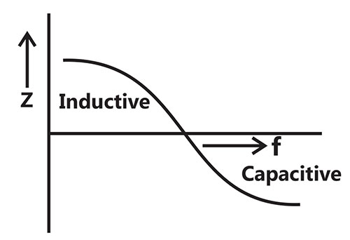
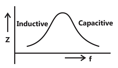
Sign in to UnlockAn inductor is connected in parallel with a capacitor as shown in the figure.
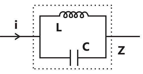
As the frequency of current i is increased, the impedance (Z) of the network varies as
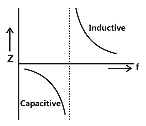
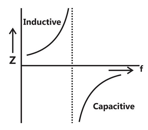
Sign in to see the solution
Log in to view the explanation, track your attempts, and keep your progress.
Sign in to UnlockA series RLC circuit is observed at two frequencies. At , we note that source voltage results in a current . At , the source voltage results in a current . The closest values for R, L, C out of the following options are










Sign in to see the solution
Log in to view the explanation, track your attempts, and keep your progress.
Sign in to UnlockTwo magnetically uncoupled inductive coils have Q factors and at the chosen operating frequency. Their respective resistances are and . When connected in series, their effective Q factor at the same operating frequency is








Sign in to see the solution
Log in to view the explanation, track your attempts, and keep your progress.
Sign in to UnlockThe Thevenin's equivalent of a circuit operating at, has and . At this frequency, the minimal realization of the Thevenin's impedance will have a



Sign in to see the solution
Log in to view the explanation, track your attempts, and keep your progress.
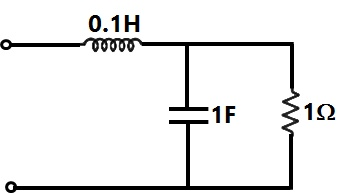
Sign in to UnlockThe resonant frequency for the given circuit will be
Sign in to see the solution
Log in to view the explanation, track your attempts, and keep your progress.
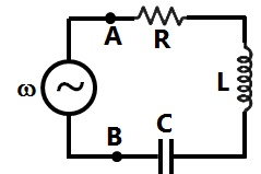
Sign in to UnlockThe R-L-C series circuit shown is supplied from a variable frequency voltage source. The admittance-locus of the R-L-C network at terminals AB for increasing frequency ω is
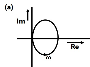
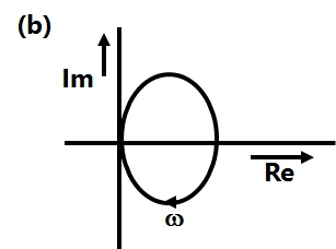
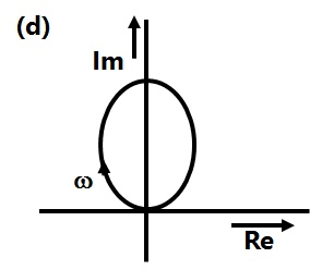
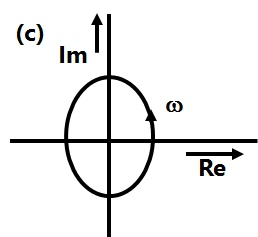
Sign in to see the solution
Log in to view the explanation, track your attempts, and keep your progress.
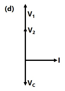
Sign in to UnlockThe circuit shown in the figure is energized by a sinusoidal voltage source at a frequency which causes resonance with a current of I.

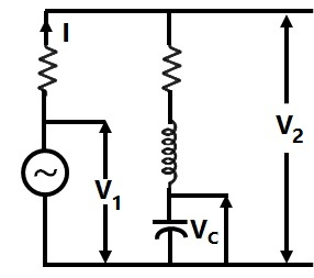
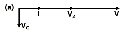
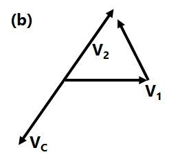
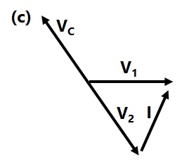
The phasor diagram which is applicable to this circuit is
Sign in to see the solution
Log in to view the explanation, track your attempts, and keep your progress.
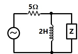
Sign in to UnlockIn the figure the value of Z in Figure, which is most appropriate to cause parallel resonance at 500 Hz, is
Sign in to see the solution
Log in to view the explanation, track your attempts, and keep your progress.
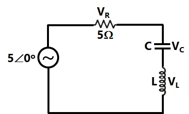
Sign in to UnlockIn the circuit of Figure, the magnitudes of and are twice that of . The inductance of the coil is



Sign in to see the solution
Log in to view the explanation, track your attempts, and keep your progress.
Sign in to UnlockA series R-L-C circuit has R = 50Ω, L = 100 μH and C = 1 μF. the lower half power frequency of the circuit is
Sign in to see the solution
Log in to view the explanation, track your attempts, and keep your progress.
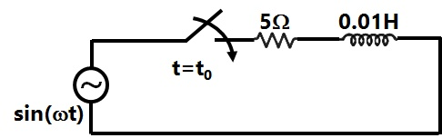
Sign in to UnlockConsider the circuit shown in Figure. If the frequency of the source is 50 Hz, then a value of which results in a transient free response is

Sign in to see the solution
Log in to view the explanation, track your attempts, and keep your progress.
Sign in to UnlockIn a series RLC circuit at resonance, the magnitude of the voltage developed across the capacitor.
Sign in to see the solution
Log in to view the explanation, track your attempts, and keep your progress.
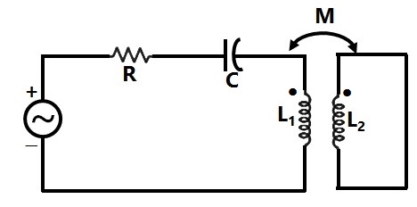
Sign in to UnlockDetermine the resonance frequency and the Q-factor of the circuit shown in figure.
Data: R = 10Ω, C = 3µF, , and M = 10 mH.


Sign in to see the solution
Log in to view the explanation, track your attempts, and keep your progress.
Sign in to UnlockA series R-L-C circuit when excited by a 10V sinusoidal voltage source of variable frequency, exhibits resonance at 100Hz and has a 3 dB bandwidth of 5Hz. The voltage across the inductor L at resonance is:
10V


200V
Sign in to see the solution
Log in to view the explanation, track your attempts, and keep your progress.
Sign in to UnlockA circuit with a resistor, inductor and capacitor in series is resonant of If all the component values are now doubled, the new resonant frequency is:


still



Sign in to see the solution
Log in to view the explanation, track your attempts, and keep your progress.
Sign in to UnlockA coil (which can be modeled as a series RL circuit) has been designed for high-Q performance at a rated voltage and a specified frequency. If the frequency of operation is doubled, and the coil is operated at the same rated voltage, then the Q-factor and the active power P consumed by the coil will be affected as follows
Sign in to see the solution
Log in to view the explanation, track your attempts, and keep your progress.
Sign in to UnlockA series R-L-C circuit has the following parameter values: , , .The Q factor of the circuit at resonance is __________



Sign in to see the solution
Log in to view the explanation, track your attempts, and keep your progress.
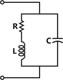
Sign in to UnlockAt resonance, the given parallel circuit constituted by an iron-coil and a capacitor behaves like
Sign in to see the solution
Log in to view the explanation, track your attempts, and keep your progress.
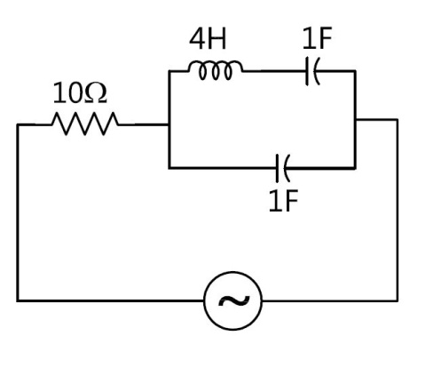
Sign in to UnlockThe following circuit (figure) resonates at
Sign in to see the solution
Log in to view the explanation, track your attempts, and keep your progress.
Sign in to Unlock