Signals and Systems
Digital Filter Design
Practice questions from Digital Filter Design.
5
Total0
Attempted0
Correct0
IncorrectThe direct form structure of an FIR (finite impulse response) filter is shown in the figure.
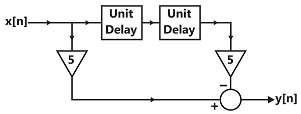
The filter can be used to approximate a
Sign in to see the solution
Log in to view the explanation, track your attempts, and keep your progress.
Sign in to UnlockAn FIR system is described by the system function . The system is

Sign in to see the solution
Log in to view the explanation, track your attempts, and keep your progress.
Sign in to UnlockA system with transfer function H(z) has impulse response h[n] defined as h[2] = 1, h[3] = –1 and h[k] = 0 otherwise. Consider the following statements.
S1: H (z) is a low-pass filter.
S2: H (z) is an FIR filter.
Which of the following is correct?
Sign in to see the solution
Log in to view the explanation, track your attempts, and keep your progress.
Sign in to UnlockThe system under consideration is an RC low-pass filter (RC-LPF) with R = 1.0 kΩ and C = 1.0 μF.
Let H(f) denote the frequency response of the RC-LPF. Let be the highest frequency such that . Then (in Hz) is


Sign in to see the solution
Log in to view the explanation, track your attempts, and keep your progress.
Sign in to UnlockThe system under consideration is an RC low-pass filter (RC-LPF) with R = 1.0 kΩ and C = 1.0 μF.
Let be the group delay function of the given RC-LPF and Then in ms, is



Sign in to see the solution
Log in to view the explanation, track your attempts, and keep your progress.
Sign in to Unlock