Digital Electronics
Data Converters
Practice questions from Data Converters.
31
Total0
Attempted0
Correct0
IncorrectA 10-bit analog-to-digital converter (ADC) has a sampling frequency of 1 MHz and a full scale voltage of 3.3 V.
For an input sinusoidal signal with frequency 500 kHz, the maximum SNR (in dB, rounded off to two decimal places) and the data rate (in Mbps) at the output of the ADC are _________, respectively.
Sign in to see the solution
Log in to view the explanation, track your attempts, and keep your progress.
Sign in to UnlockThe signal-to-noise ratio (SNR) of an ADC with a full-scale sinusoidal input is given to be 61.96 . The resolution of the ADC is __________ (rounded off to the nearest integer). bits.

Sign in to see the solution
Log in to view the explanation, track your attempts, and keep your progress.
Sign in to UnlockA sample and hold circuit is implemented using a resistive switch and a capacitor with a time constant of . The time for sampling switch to stay closed to charge a capacitor adequately to full scale voltage of with 12-bit accuracy is ________ .


(rounded off to two decimal places)
Sign in to see the solution
Log in to view the explanation, track your attempts, and keep your progress.
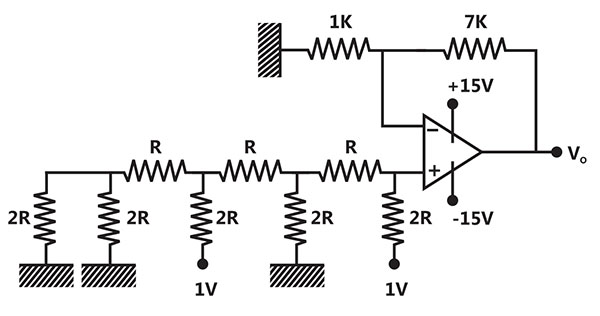
Sign in to UnlockConsider the circuit shown with an ideal OPAMP. The output voltage is _______ V (rounded off to two decimal places).

Sign in to see the solution
Log in to view the explanation, track your attempts, and keep your progress.
Sign in to UnlockAn 8-bit unipolar (all analog output values are positive) digital-to-analog converter (DAC) has a full-scale voltage range from 0V to 7.68V. If the digital input code is 10010110 (the leftmost bit is MSB, then the analog output voltage of the DAC (rounded off to one decimal place) is _______ V.
Sign in to see the solution
Log in to view the explanation, track your attempts, and keep your progress.
Sign in to UnlockA 10-bit D/A converter is calibrated over the full range from 0 to . If the input to the converter is (in hex), the output (rounded off to three decimal places) is _________ V.


Sign in to see the solution
Log in to view the explanation, track your attempts, and keep your progress.
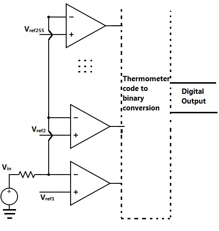
Sign in to UnlockIn an N bit flash ADC, the analog voltage is fed simultaneously to comparators. The output of the comparators is then encoded to a binary format using digital circuits. Assume that the analog voltage source (whose output is being converted to digital format) has a source resistance of 75 Ω as shown in the circuit diagram below and the input capacitance of each comparator is 8pF. The output must settle to an accuracy of 1/2 LSB even for a full scale input change for proper conversion. Assume that the time taken by the thermometer to binary encoder is negligible.


If the flash ADC has 8 bit resolution, which one of the following alternatives is closest to the maximum sampling rate?
Sign in to see the solution
Log in to view the explanation, track your attempts, and keep your progress.
Sign in to UnlockConsider a four bit D to A converter. The analog value corresponding to digital signals of values 0000 and 0001 are 0 V and 0.0625 V respectively. The analog value (in Volts) corresponding to the digital signal 1111 is ________.
Sign in to see the solution
Log in to view the explanation, track your attempts, and keep your progress.
Sign in to UnlockAn analog voltage in the range 0 to 8 V is divided in 16 equal intervals for conversion to 4-bit digital output. The maximum quantization error (in V) is _________.
Sign in to see the solution
Log in to view the explanation, track your attempts, and keep your progress.
Sign in to UnlockFor a given sample-and-hold circuit, if the value of the hold capacitor is increased, then
Sign in to see the solution
Log in to view the explanation, track your attempts, and keep your progress.
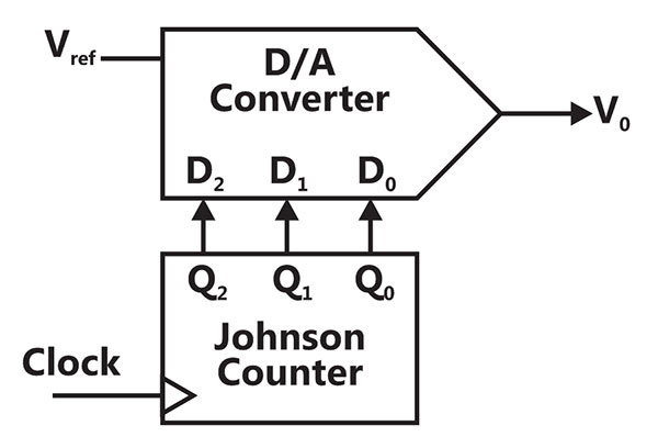
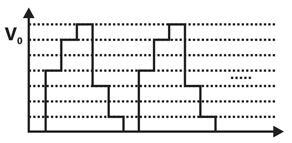
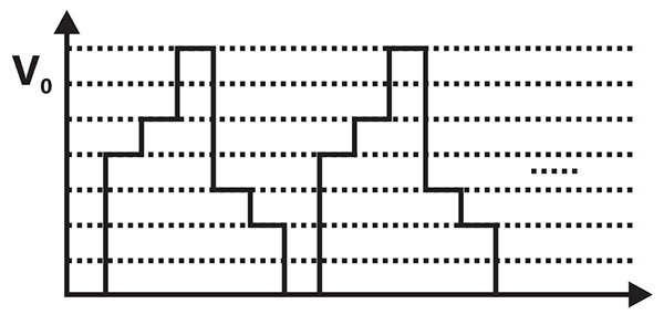
Sign in to UnlockThe output of a 3-stage Johnson (twisted-ring) counter is fed to a digital-to-analog (D/A) converter as shown in the figure below. Assume all states of the counter to be unset initially. The waveform which represents the D/A converter output is

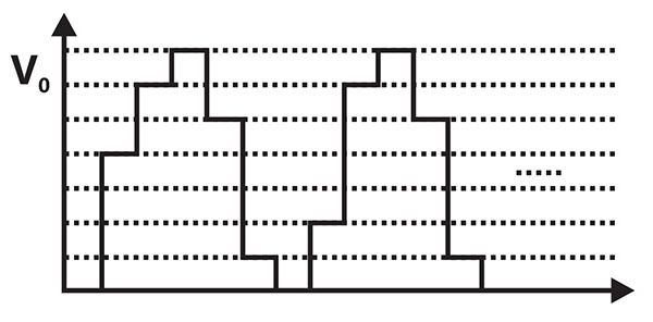
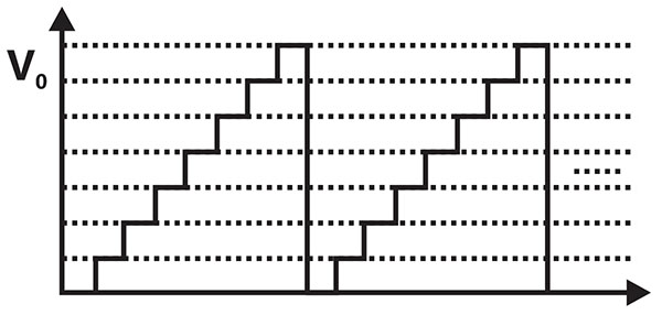
Sign in to see the solution
Log in to view the explanation, track your attempts, and keep your progress.
Sign in to UnlockIn the following circuit, the comparator output is logic “1” if and is logic “0” otherwise. The D/A conversion is done as per the relation

volts, where (MSB) , and (LSB) are the counter outputs.


The counter starts from the clear state.
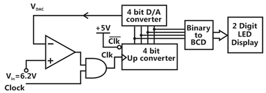
The stable reading of the LED displays is
Sign in to see the solution
Log in to view the explanation, track your attempts, and keep your progress.
Sign in to UnlockIn the following circuit, the comparator output is logic “1” if and is logic “0” otherwise. The D/A conversion is done as per the relation
volts, where (MSB) , and (LSB) are the counter outputs.
The counter starts from the clear state.
The magnitude of the error between and at steady state in volts is


Sign in to see the solution
Log in to view the explanation, track your attempts, and keep your progress.
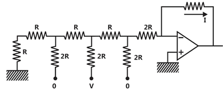
Sign in to UnlockIn the Digital-to-Analog converter circuit shown in the figure below, and R =10kΩ.

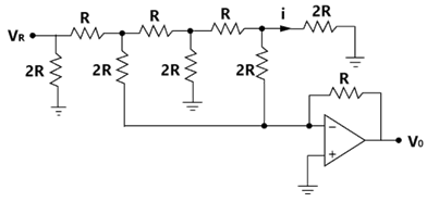
The current i is
Sign in to see the solution
Log in to view the explanation, track your attempts, and keep your progress.
Sign in to UnlockIn the Digital-to-Analog converter circuit shown in the figure below, and R =10kΩ.
The voltage is
Sign in to see the solution
Log in to view the explanation, track your attempts, and keep your progress.
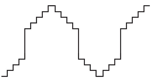
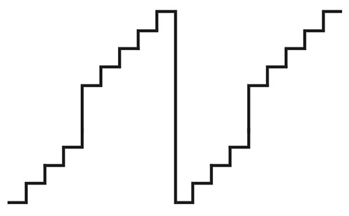
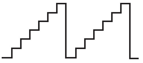
Sign in to UnlockA 4-bit D/A converter is connected to a free-running 3-bit UP counter, as shown in the following figure. Which of the following waveforms will be observed at?

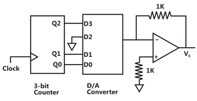
In the figure shown above, the ground has been shown by the symbol

Sign in to see the solution
Log in to view the explanation, track your attempts, and keep your progress.
Sign in to UnlockThe minimum number of comparators required to build an 8 it flash ADC is
Sign in to see the solution
Log in to view the explanation, track your attempts, and keep your progress.
Sign in to UnlockThe circuit shown in figure is a 4-bit DAC. The input bits 0 and 1 are represented by 0 and 5 V respectively. The OP AMP is ideal, but all the resistances and the 5V inputs have a tolerance of . The specification (rounded to the nearest multiple of 5%) for the tolerance of the DAC is


Sign in to see the solution
Log in to view the explanation, track your attempts, and keep your progress.
Sign in to UnlockThe number of comparators required in a 3-bit comparator-type ADC is
Sign in to see the solution
Log in to view the explanation, track your attempts, and keep your progress.
Sign in to UnlockA monochrome video signal that ranges from 0 to 8V is digitized using an 8-bit ADC.
(a) Determine the resolution of the ADC in V/bit.
(b) Calculate the mean squared quantization error.
(c) Suppose the ADC is counter-controlled. The counter is up-count and positive-edge triggered with a clock frequency of 1MHz.
What is the time taken in seconds to get a digital equivalent of 1.59V?
(a) Resolution = 0.03125V
(b)

(c)

(a) Resolution = 0.02546V
Sign in to see the solution
Log in to view the explanation, track your attempts, and keep your progress.
Sign in to UnlockAn 8 bit successive approximation analog to digital converter has full scale reading of 2.55 V and its conversion time for an analog input of 1V is . The conversion for a 2V input will be


Sign in to see the solution
Log in to view the explanation, track your attempts, and keep your progress.
Sign in to UnlockThe number of comparators in a 4 bit flash ADC is
Sign in to see the solution
Log in to view the explanation, track your attempts, and keep your progress.
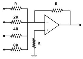
Sign in to UnlockFor the 4 bit DAC shown in Figure, the output voltage is

Sign in to see the solution
Log in to view the explanation, track your attempts, and keep your progress.
Sign in to UnlockThe resolution of a 4-bit counting ADC is 0.5 volts. For an analog input of 6.6 volts, the digital output of the ADC will be
Sign in to see the solution
Log in to view the explanation, track your attempts, and keep your progress.
Sign in to UnlockThe advantage of using a dual slope ADC in a digital voltmeter is that
Sign in to see the solution
Log in to view the explanation, track your attempts, and keep your progress.
Sign in to UnlockThe current I through resistance r in the circuit shown in Figure is


Sign in to see the solution
Log in to view the explanation, track your attempts, and keep your progress.
Sign in to UnlockA 12-bit ADC is operating with a sec clock period and the total conversion time is seen to be secs. The ADC must be of the


Sign in to see the solution
Log in to view the explanation, track your attempts, and keep your progress.
Sign in to UnlockA 10-bit ADC with a full scale output voltage of 10.24 V is designed to have aLSB/2 accuracy. If the ADC is calibrated at and the operating temperature range from to , then the maximum net temperature coefficient of the ADC should not exceed


Sign in to see the solution
Log in to view the explanation, track your attempts, and keep your progress.
Sign in to UnlockFor an ADC, match the following
(A) Flash converter
(B) Dual slope converter
(C) Successive approximation
(1) Requires a conversion time of the order of a few seconds
(2) Requires a digital-to-analog converter
(3) Minimizes the effect of power supply interference
(4) Requires a very high complex hardware
(5) Is a tracking A/D converters
Sign in to see the solution
Log in to view the explanation, track your attempts, and keep your progress.
Sign in to UnlockMatch the following
Type of ADC
(A) Successive
(B) Dual-slope
(C) Parallel Comparator
Maximum conversion for 8 bit ADC in clock cycles.
(1) 1
(2) 8
(3) 16
(4) 256
(5) 512
Sign in to see the solution
Log in to view the explanation, track your attempts, and keep your progress.
Sign in to UnlockDual slope integration type Analog-to-digital converters provide
Sign in to see the solution
Log in to view the explanation, track your attempts, and keep your progress.
Sign in to Unlock