Network Analysis
Two Port Network
Practice questions from Two Port Network.
39
Total0
Attempted0
Correct0
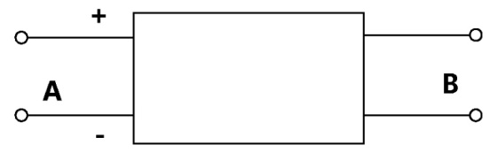
IncorrectThe -parameter matrix of a two port network relates the port voltages and port currents as follows:


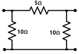
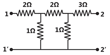
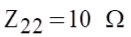
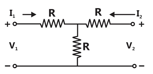
The -parameter matrix (with each entry in Ohms) of the network shown below is


Sign in to see the solution
Log in to view the explanation, track your attempts, and keep your progress.
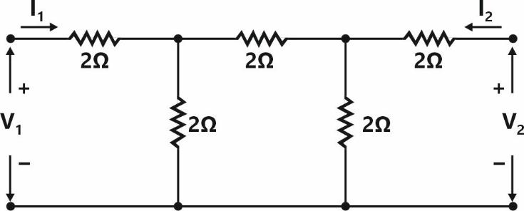
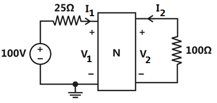
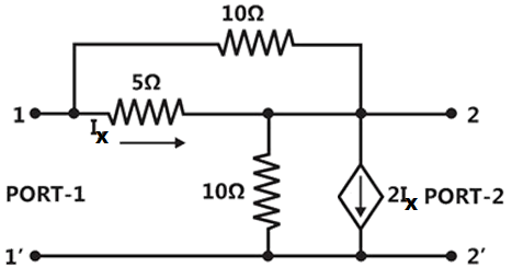
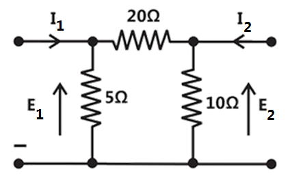
Sign in to UnlockFor the two port network shown below, the value of the parameter (in Siemens) is__________.

Sign in to see the solution
Log in to view the explanation, track your attempts, and keep your progress.
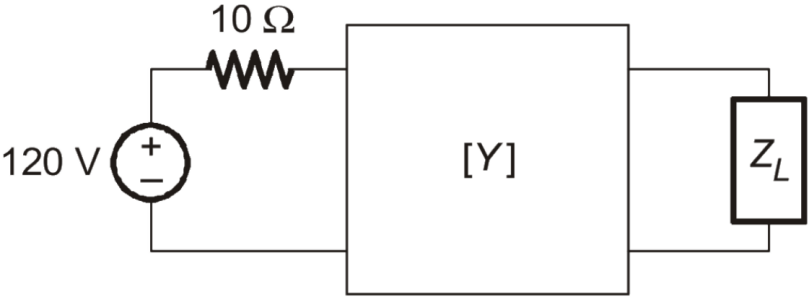
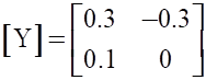
Sign in to UnlockFor the two port network shown below, the [Y]-parameters is given as

The value of load impedance , in , for maximum power transfer will be _________.


(rounded off to the nearest integer).
Sign in to see the solution
Log in to view the explanation, track your attempts, and keep your progress.
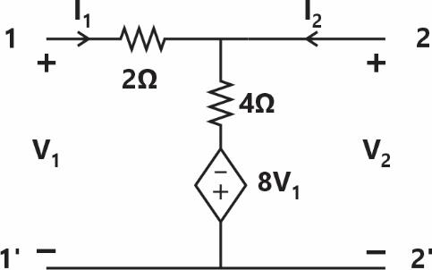
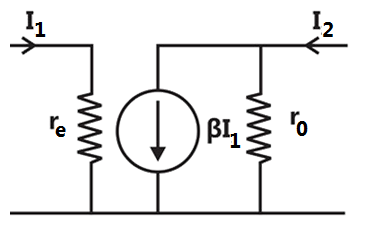
Sign in to UnlockThe h-parameters of a two port network are shown below. The condition for the maximum small signal voltage gain is

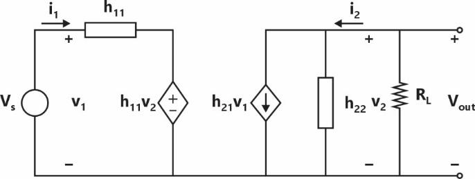
very high and


very high, very high and


very high, very high and


very high and very high

Sign in to see the solution
Log in to view the explanation, track your attempts, and keep your progress.
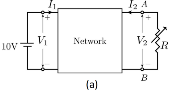
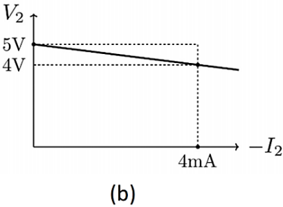
Sign in to Unlocklinear 2-port network is shown in Fig. (a). An ideal DC voltage source of is connected across Port 1. A variable resistance is connected across Port 2. As is varied, the measured voltage and current at Port 2 is shown in Fig. (b) as a versus plot. Note that for , , and for .


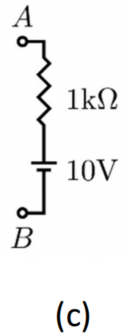
When the variable resistance at ort 2 is replaced by the load shown in Fig. (c), the current is _________ (rounded off to one decimal place).


Sign in to see the solution
Log in to view the explanation, track your attempts, and keep your progress.
Sign in to UnlockConsider the two-port network shown in the figure.
The admittances parameters, in Siemens, are


Sign in to see the solution
Log in to view the explanation, track your attempts, and keep your progress.
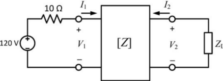
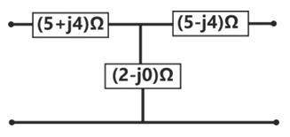
Sign in to UnlockIn the given circuit, the two-port network has the impedance matrix . The value of for which maximum power is transferred to the load is __________ .


Sign in to see the solution
Log in to view the explanation, track your attempts, and keep your progress.
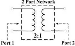
Sign in to UnlockFor a 2-port network consisting of an ideal lossless transformer, the parameter (rounded off to two decimal places) for a reference impedance of , is _______.


Sign in to see the solution
Log in to view the explanation, track your attempts, and keep your progress.
Sign in to UnlockThe ABCD matrix for a two-port network is defined by:


The parameter B for the given two-port network (in ohms. correct to two decimal places) is _______.
Sign in to see the solution
Log in to view the explanation, track your attempts, and keep your progress.
Sign in to UnlockConsider a two-port network with the transmission matrix: If the network is reciprocal, then


Sign in to see the solution
Log in to view the explanation, track your attempts, and keep your progress.
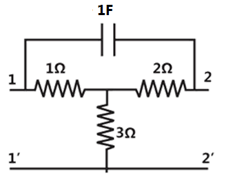
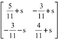
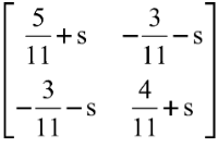
Sign in to UnlockThe z-parameter matrix for the two-port network shown is , where the entries are in. Suppose.


Then the value of (in ) equals ________.

Sign in to see the solution
Log in to view the explanation, track your attempts, and keep your progress.
Sign in to UnlockThe z-parameter matrix for the two-port network shown is


Sign in to see the solution
Log in to view the explanation, track your attempts, and keep your progress.
Sign in to UnlockIn The 2-port admittance matrix of the circuit shown is given by


Sign in to see the solution
Log in to view the explanation, track your attempts, and keep your progress.
Sign in to UnlockThe ABCD parameters of the following 2-port network are


Sign in to see the solution
Log in to view the explanation, track your attempts, and keep your progress.
Sign in to UnlockA two-port network has scattering parameters given by. If port-2 of the two-port is short circuited, the parameter for the resultant one-port network is


Sign in to see the solution
Log in to view the explanation, track your attempts, and keep your progress.
Sign in to UnlockIn the h-parameter model of the 2-port network given in the figure shown, the value of (in S) is ______.

Sign in to see the solution
Log in to view the explanation, track your attempts, and keep your progress.
Sign in to UnlockFor the two-port network shown in the figure, the impedance (Z) matrix (in Ω) is


Sign in to see the solution
Log in to view the explanation, track your attempts, and keep your progress.
Sign in to UnlockWith 10 V dc connected at port A in the linear nonreciprocal two-port network shown below, the following were observed
(i) 1Ω connected at port B draws a current of 3 A
(ii) 2.5 Ω connected at port B draws a current of 2 A
With 10 V dc connected at port A, the current drawn by 7 Ω connected at port B is
Sign in to see the solution
Log in to view the explanation, track your attempts, and keep your progress.
Sign in to UnlockWith 10 V dc connected at port A in the linear nonreciprocal two-port network shown below, the following were observed
(i) 1Ω connected at port B draws a current of 3 A
(ii) 2.5 Ω connected at port B draws a current of 2 A
For the same network, with 6 V dc connected at port A, 1 Ω connected at port B draws 7/3 A. If 8 V dc is connected to port A, the open circuit voltage at port B is
Sign in to see the solution
Log in to view the explanation, track your attempts, and keep your progress.
Sign in to UnlockIn the circuit shown below, the network N is described by the following Y matrix:
. The voltage gain is


Sign in to see the solution
Log in to view the explanation, track your attempts, and keep your progress.
Sign in to UnlockFor the two-port network shown below, the short-circuit admittance parameter matrix is


Sign in to see the solution
Log in to view the explanation, track your attempts, and keep your progress.
Sign in to UnlockA two-port network shown below is excited by external dc sources. The voltages and the currents are measured with voltmeters, and ammeters,(all assumed to be ideal), as indicated. Under following switch conditions, the readings obtained are:


(i) -Open,-Closed ; = 0 A, = 4.5 V, = 1.5V, = 1 A


(ii) -Closed,-Open ; = 4 A,= 6 V, = 6 V, = 0 A
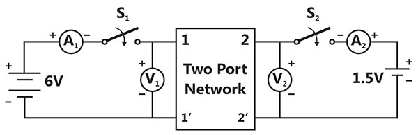
The z-parameter matrix for this network is


Sign in to see the solution
Log in to view the explanation, track your attempts, and keep your progress.
Sign in to UnlockA two-port network shown below is excited by external dc sources. The voltages and the currents are measured with voltmeters, and ammeters,(all assumed to be ideal), as indicated. Under following switch conditions, the readings obtained are:
(i) -Open,-Closed ; = 0 A, = 4.5 V, = 1.5V, = 1 A
(ii) -Closed,-Open ; = 4 A,= 6 V, = 6 V, = 0 A
The h-parameter matrix for this network is


Sign in to see the solution
Log in to view the explanation, track your attempts, and keep your progress.
Sign in to UnlockA two port network is represented by ABCD parameters given by . If port-2 is terminated by , the input impedance seen at port-1 is given by


Sign in to see the solution
Log in to view the explanation, track your attempts, and keep your progress.
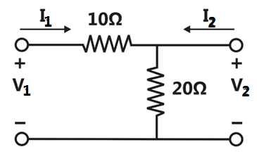
Sign in to UnlockIn the two port network shown in the figure below, and are, respectively


and


0 and

0 and
and
Sign in to see the solution
Log in to view the explanation, track your attempts, and keep your progress.
Sign in to UnlockThe ABCD parameters of an ideal n:1 transformer shown in figure are . The value of X will be

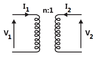
n


Sign in to see the solution
Log in to view the explanation, track your attempts, and keep your progress.
Sign in to UnlockThe h parameters of the circuit shown in figure are


Sign in to see the solution
Log in to view the explanation, track your attempts, and keep your progress.
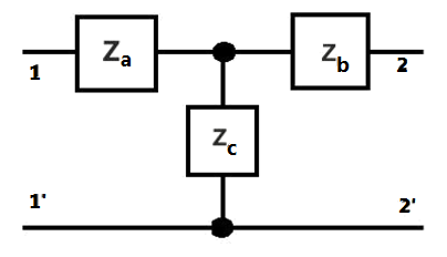
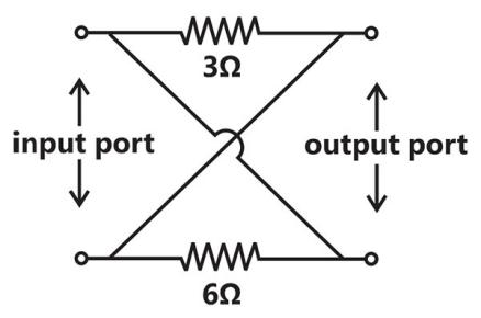
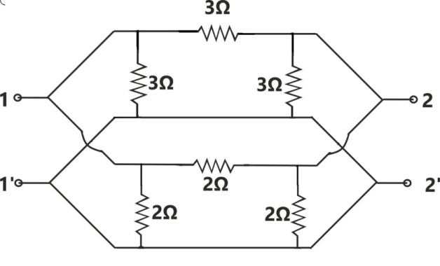
Sign in to UnlockFor the lattice circuit shown in Figure, and . The values of the open circuit impedance parameters are


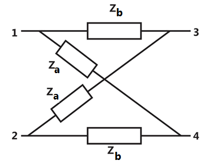


Sign in to see the solution
Log in to view the explanation, track your attempts, and keep your progress.
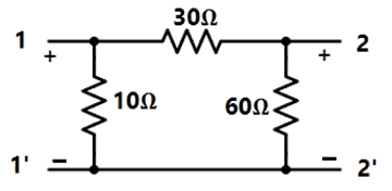
Sign in to UnlockThe impedance parameters and of the two-port network in figure are


and


and


and
and

Sign in to see the solution
Log in to view the explanation, track your attempts, and keep your progress.
Sign in to UnlockConsider the network in Figure.
Short-circuit admittance parameters
Open-circuit impedance

Short-circuit admittance parameters
Open-circuit impedance
Sign in to see the solution
Log in to view the explanation, track your attempts, and keep your progress.
Sign in to UnlockThe admittance parameter in the 2-port network in Figure is

Sign in to see the solution
Log in to view the explanation, track your attempts, and keep your progress.
Sign in to UnlockThe Z parameters and for the 2-port network in figure are


;


;


;

;

Sign in to see the solution
Log in to view the explanation, track your attempts, and keep your progress.
Sign in to UnlockThe admittance parameters of a 2-port network shown in figure are given by mho, mho, mho, mho. The output port is terminated with a load admittance mho.


For


For


For
A source in series with a 0.25Ω resistor is connected to the input port.


Sign in to see the solution
Log in to view the explanation, track your attempts, and keep your progress.
Sign in to UnlockA 2-port network is shown in Figure. The parameters for this network can be given by


Sign in to see the solution
Log in to view the explanation, track your attempts, and keep your progress.
Sign in to UnlockThe short-circuit admittance matrix of a two-port network is. The two port network is

Sign in to see the solution
Log in to view the explanation, track your attempts, and keep your progress.
Sign in to UnlockThe condition that a 2-port network is reciprocal, can be expressed in terms of its ABCD parameters as . ( True=1, False=0)

Sign in to see the solution
Log in to view the explanation, track your attempts, and keep your progress.
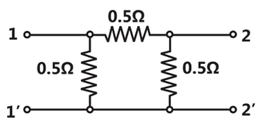
Sign in to UnlockFind the Y-parameters (short circuit admittance parameters) for the network shown in figure.
None of these
Sign in to see the solution
Log in to view the explanation, track your attempts, and keep your progress.
Sign in to UnlockFor a port network to be reciprocal


Sign in to see the solution
Log in to view the explanation, track your attempts, and keep your progress.
Sign in to UnlockTwo two-port networks are connected in cascade. The combination is to be represented as a single two-port network. The parameters of the network are obtained by multiplying the individual
Sign in to see the solution
Log in to view the explanation, track your attempts, and keep your progress.
Sign in to Unlock