EMFT - ECE
Transmission Lines
Practice questions from Transmission Lines.
62
Total0
Attempted0
Correct0
IncorrectA lossless transmission line is terminated with a load of .



If the average incident power on the line is 10 mW, then the average power delivered to the load (in mW, rounded off to one decimal place) is ________.
Sign in to see the solution
Log in to view the explanation, track your attempts, and keep your progress.
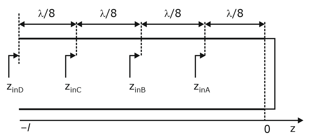
Sign in to UnlockConsider a lossless transmission line terminated with a short circuit as shown in the figure below. As one moves towards the generator from the load, the normalized impedances , and (indicated in the figure) are_______.






Sign in to see the solution
Log in to view the explanation, track your attempts, and keep your progress.
Sign in to UnlockA lossless transmission line with characteristic impedance is terminated with an unknown load. The magnitude of the reflection co-efficient is . As one moves towards the generator from the load, the maximum value of the input impedance magnitude looking towards the load (in ) is ________.



Sign in to see the solution
Log in to view the explanation, track your attempts, and keep your progress.
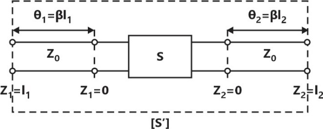
Sign in to UnlockThe S-parameters of a two port network is given as

with reference to . Two lossless transmission line sections of electrical lengths and are added to the input and output ports for measurement purposes, respectively. The Sparameters of the resultant two port network is








Sign in to see the solution
Log in to view the explanation, track your attempts, and keep your progress.
Sign in to UnlockA transparent dielectric coating is applied to glass to eliminate the reflection of red light . The minimum thickness of the dielectric coating, in , that can be used is ________. (rounded off to two decimal places).



Sign in to see the solution
Log in to view the explanation, track your attempts, and keep your progress.
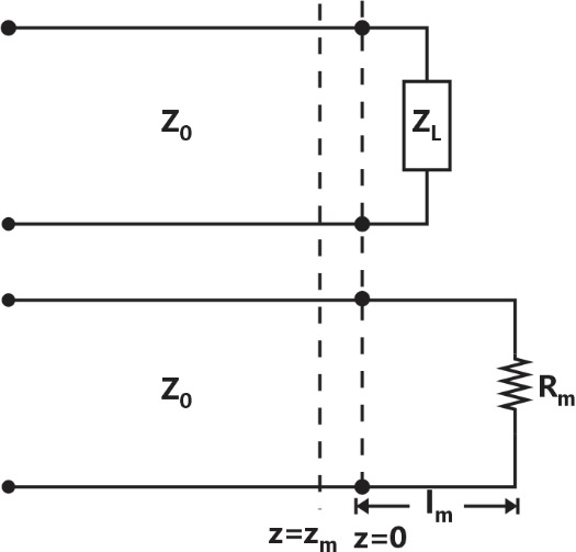
Sign in to UnlockThe standing wave ratio on a lossless transmission line terminated in an unknown load impedance is found to be 2.0. The distance between successive voltage minima is 30 cm and the first minimum is located at 10 cm from the load. can be replaced by an equivalent length and terminating resistance of the same line. The value of and , respectively, are








Sign in to see the solution
Log in to view the explanation, track your attempts, and keep your progress.
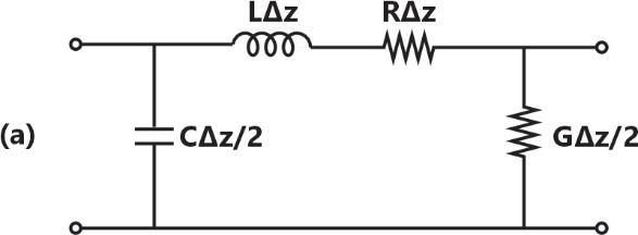
Sign in to UnlockThe following circuit(s) representing a lumped element equivalent of an infinitesimal section of a transmission line is/are
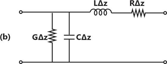
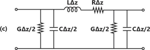
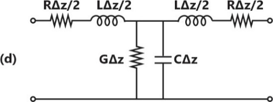
Sign in to see the solution
Log in to view the explanation, track your attempts, and keep your progress.
Sign in to UnlockThe impedance matching network shown in the figure is to match a lossless line having characteristic impedance with a load impedance . A quarter-wave line having a characteristic impedance is connected to . Two stubs having characteristic impedance of each are connected to this quarter-wave line. One is a short-circuited (S.C.) sub of length connected across and the other one is an open-circuited (O.C.) stub of length connected across RS.



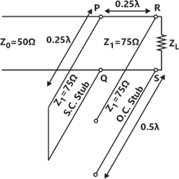
The impedance matching is achieved when the real part of is


Sign in to see the solution
Log in to view the explanation, track your attempts, and keep your progress.
Sign in to UnlockThe impedances , for all in the range , map to the Smith chart as



a circle of radius 0.5 with centre at .

a point at the centre of the chart.
a line passing through the centre of the chart.
a circle of radius 1 with centre at .

Sign in to see the solution
Log in to view the explanation, track your attempts, and keep your progress.
Sign in to UnlockA transmission line of length and having a characteristic impedance of is terminated with a load of . The impedance (rounded off to two decimal places) seen at the input end of the transmission line is ________.


Sign in to see the solution
Log in to view the explanation, track your attempts, and keep your progress.
Sign in to UnlockA lossy transmission line has resistance per unit length. The line is distortion-less and has characteristic impedance of . The attenuation constant (in Np/m, correct to three decimal places) of the line is_______


Sign in to see the solution
Log in to view the explanation, track your attempts, and keep your progress.
Sign in to UnlockThe points P, Q, and R shown on the Smith chart (normalized impedance chart) in the following figure represent:

Sign in to see the solution
Log in to view the explanation, track your attempts, and keep your progress.
Sign in to UnlockA two-wire transmission line terminates in a television set. The VSWR measured on the line is 5.8. The percentage of power that is reflected from the television set is ___________
Sign in to see the solution
Log in to view the explanation, track your attempts, and keep your progress.
Sign in to UnlockThe propagation constant of a lossy transmission line is (2 + j5) and its characteristic impedance is (50+ jo)Ω at ω = rad . The values of the line constants L, C, R, G are, respectively,



Sign in to see the solution
Log in to view the explanation, track your attempts, and keep your progress.
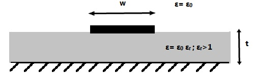
Sign in to UnlockA lossless micro strip transmission line consists of a trace of width. It is drawn over a practically infinite ground plane and is separated by a dielectric slab of thickness t and relative permittivity. The inductance per unit length and the characteristic impedance of this line are L and, respectively.


Which one of the following inequalities is always satisfied?




Sign in to see the solution
Log in to view the explanation, track your attempts, and keep your progress.
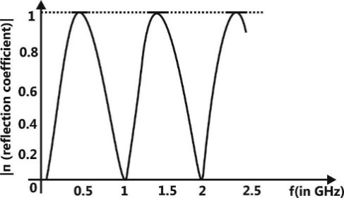
Sign in to UnlockA microwave circuit consisting of lossless transmission lines and is shown in the figure. The plot shows the magnitude of the input reflection coefficient as a function of frequency f. The phase velocity of the signal in the transmission lines is m/s.




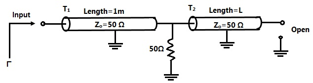
The length L (in meters) of is ________.
Sign in to see the solution
Log in to view the explanation, track your attempts, and keep your progress.
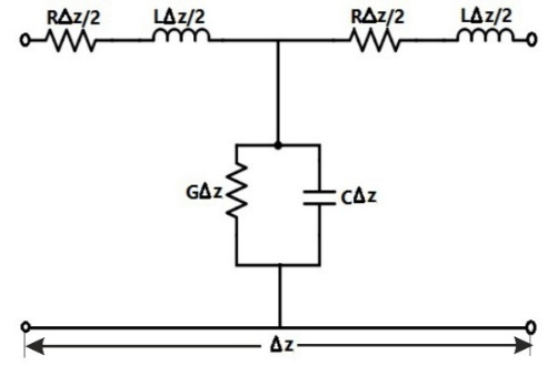
Sign in to UnlockA coaxial cable is made of two brass conductors. The spacing between the conductors is filled with Teflon . Which one of the following circuits can represent the lumped element model of a small piece of this cable having length ∆z?

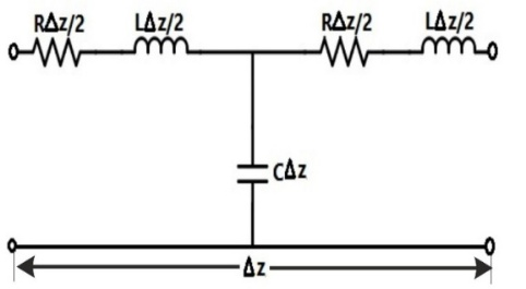

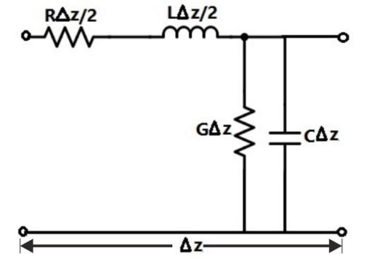
Sign in to see the solution
Log in to view the explanation, track your attempts, and keep your progress.
Sign in to UnlockConsider the 3 m long lossless air-filled transmission line shown in the figure. It has a characteristic impedance of 120π Ω, is terminated by a short circuit, and is excited with a frequency of 37.5MHz. What is the nature of the input impedance ?

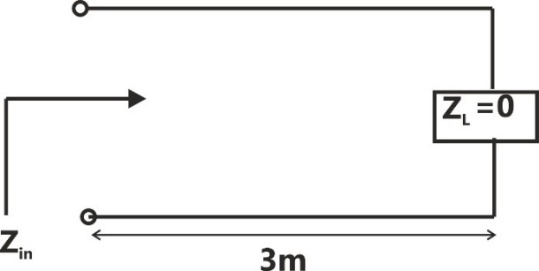
Sign in to see the solution
Log in to view the explanation, track your attempts, and keep your progress.
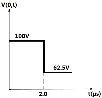
Sign in to UnlockA 200 m long transmission line having parameters shown in the figure is terminated into a load . The line is connected to a 400 V source having source resistance through a switch, which is closed at t = 0. The transient response of the circuit at the input of the line (z = 0) is also drawn in the figure. The value of (in Ω) is ________.


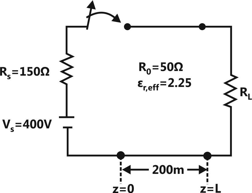
Sign in to see the solution
Log in to view the explanation, track your attempts, and keep your progress.
Sign in to UnlockFor a parallel plate transmission line, let ν be the speed of propagation and Z be the characteristic impedance. Neglecting fringe effects, a reduction of the spacing between the plates by a factor of two results in
Sign in to see the solution
Log in to view the explanation, track your attempts, and keep your progress.
Sign in to UnlockThe input impedance of a section of a lossless transmission line of characteristic impedance 50 Ω is found to be real when the other end is terminated by a load . If X is 30Ω , the value of R ( in Ω ) is _______.


Sign in to see the solution
Log in to view the explanation, track your attempts, and keep your progress.
Sign in to UnlockTo maximize power transfer, a lossless transmission line is to be matched to a resistive load impedance via a λ/4 transformer as shown.
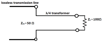
The characteristic impedance (in Ω) of the λ/4 transformer is _________.
Sign in to see the solution
Log in to view the explanation, track your attempts, and keep your progress.
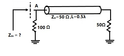
Sign in to UnlockIn the transmission line shown, the impedance (in ohms) between node A and the ground is _________.

Sign in to see the solution
Log in to view the explanation, track your attempts, and keep your progress.
Sign in to UnlockIn the following figure, the transmitter Tx sends a wideband modulated RF signal via a coaxial cable to the receiver Rx. The output impedance of Tx, the characteristic impedance of the cable and the input impedance of Rx are all real.


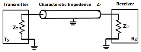
Which one of the following statements is TRUE about the distortion of the received signal due to impedance mismatch?
The signal gets distorted if , irrespective of the value of

The signal gets distorted if , irrespective of the value of

Signal distortion implies impedance mismatch at both ends: and
Impedance mismatches do NOT result in signal distortion but reduce power transfer efficiency
Sign in to see the solution
Log in to view the explanation, track your attempts, and keep your progress.
Sign in to UnlockA coaxial cable with an inner diameter of 1 mm and outer diameter of 2.4 mm is filled with a dielectric of relative permittivity 10.89. Given = 4π × H/m, , the characteristic impedance of the cable is



Sign in to see the solution
Log in to view the explanation, track your attempts, and keep your progress.
Sign in to UnlockA transmission line with a characteristic impedance of 100 Ω is used to match a 50 Ω section to a 200 Ω section. If the matching is to be done both at 429 MHz and 1 GHz, the length of the transmission line can be approximately
Sign in to see the solution
Log in to view the explanation, track your attempts, and keep your progress.
Sign in to Unlockis terminated by a load. When excited by a sinusoidal voltage source at 10 GHz, the phase difference between two points spaced 2 mm apart on the line is found to be radians. The phase velocity of the wave along the line is






Sign in to see the solution
Log in to view the explanation, track your attempts, and keep your progress.
Sign in to UnlockA transmission line of characteristic impedance is terminated in a load impedance . The VSWR of the line is measured as 5 and the first of the voltage maxima in the line is observed at a distance of from the load. The value of is






Sign in to see the solution
Log in to view the explanation, track your attempts, and keep your progress.
Sign in to UnlockA transmission line has a characteristic impedance of and a resistance of. If the line is distortion less, the attenuation constant (in Np/m) is

Sign in to see the solution
Log in to view the explanation, track your attempts, and keep your progress.
Sign in to UnlockIn the circuit shown, all the transmission line sections are lossless. The Voltage Standing Wave Ration (VSWR) on the 60W line is
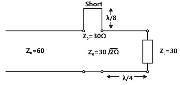
Sign in to see the solution
Log in to view the explanation, track your attempts, and keep your progress.
Sign in to UnlockA transmission line terminates in two branches, each of length , as shown. The branches are terminated by loads. The lines are lossless and have the characteristic impedances shown. Determine the impedance as seen by the source.

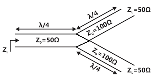



Sign in to see the solution
Log in to view the explanation, track your attempts, and keep your progress.
Sign in to UnlockOne end of a loss-less transmission line having the characteristic impedance of and length of 1cm is short-circuited. At 3GHz, the input impedance at the other end of the transmission line is

Sign in to see the solution
Log in to view the explanation, track your attempts, and keep your progress.
Sign in to UnlockA load of 50 Ω is connected in shunt in a 2-wire transmission line of Ω as shown in the figure. The 2-portscattering parameter matrix (S-matrix) of the shunt element is

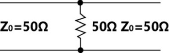




Sign in to see the solution
Log in to view the explanation, track your attempts, and keep your progress.
Sign in to UnlockThe parallel branches of a 2-wire transmission line are terminated in 100 Ω and 200 Ω resistors as shown in the figure. The characteristic impedance of the line is –50Ω and each section has a length of The voltage reflection coefficient at the input is






Sign in to see the solution
Log in to view the explanation, track your attempts, and keep your progress.
Sign in to UnlockA transmission line is feeding 1 watt of power to a born antenna having a gain of 10 dB. The antenna is matched to the transmission line. The total power radiated by the horn antenna into the free-space is:
Sign in to see the solution
Log in to view the explanation, track your attempts, and keep your progress.
Sign in to UnlockA 30-Volts battery with zero source resistance is connected to a coaxial line of characteristic impedance of 50 Ohms at t = 0 second terminated in an unknown resistive load. The line length is that it takes for an electromagnetic wave to travel from source end to load end and vice-versa. At, the voltage at the load end is found to be 40 Volts.


The load resistance is
Sign in to see the solution
Log in to view the explanation, track your attempts, and keep your progress.
Sign in to UnlockA 30-Volts battery with zero source resistance is connected to a coaxial line of characteristic impedance of 50 Ohms at t = 0 second terminated in an unknown resistive load. The line length is that it takes for an electromagnetic wave to travel from source end to load end and vice-versa. At, the voltage at the load end is found to be 40 Volts.
The steady-state current through the load resistance is:
Sign in to see the solution
Log in to view the explanation, track your attempts, and keep your progress.
Sign in to UnlockMany circles are drawn in a smith chart used for transmission line calculations. The circles shown in figure represent
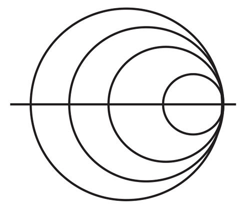
Sign in to see the solution
Log in to view the explanation, track your attempts, and keep your progress.
Sign in to UnlockCharacteristic impedance of a transmission line is . Input impedance of the open circuited line is . When the transmission line is short-circuited the value of the input impedance will be




Sign in to see the solution
Log in to view the explanation, track your attempts, and keep your progress.
Sign in to UnlockVoltage standing wave pattern in a lossless transmission line with characteristic impedance and a resistive load is shown in figure
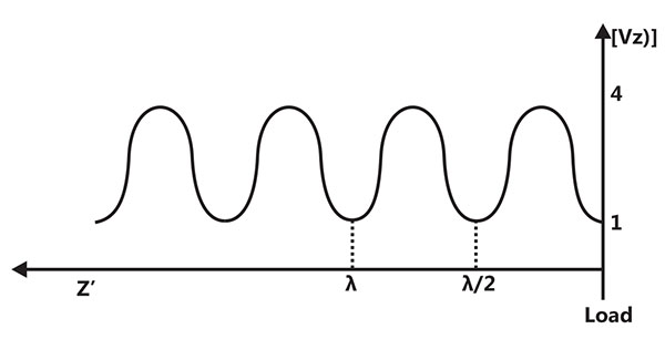
The value of the load resistance is


Sign in to see the solution
Log in to view the explanation, track your attempts, and keep your progress.
Sign in to UnlockVoltage standing wave pattern in a lossless transmission line with characteristic impedance and a resistive load is shown in figure.
The reflection coefficient is given by
Sign in to see the solution
Log in to view the explanation, track your attempts, and keep your progress.
Sign in to UnlockConsider a 300Ω quarter-wave long (at 1 GHz) transmission line as shown in Figure. It is connected to a 10V, 50Ω sources at one end and is left open circuited at the other end. The magnitude of the voltage at the open circuit end of the line is
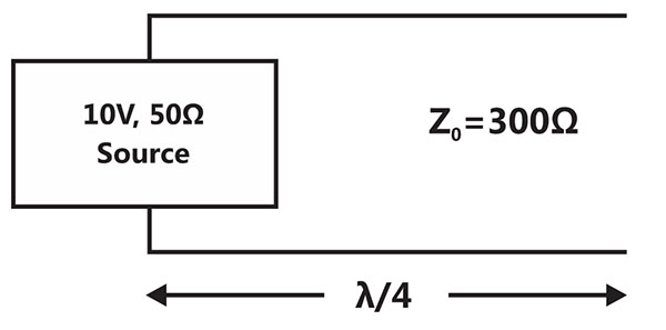
10 V
5 V
60 V

Sign in to see the solution
Log in to view the explanation, track your attempts, and keep your progress.
Sign in to UnlockConsider impedance marked with point P in an impedance smith chart as shown in Fig.Q.88. The movement from point P along a constant resistance circle in the clockwise direction by an angle 45º is equivalent to

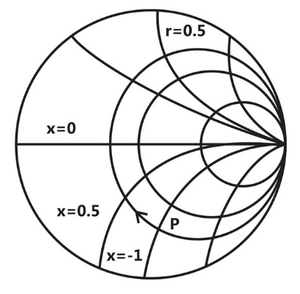
Sign in to see the solution
Log in to view the explanation, track your attempts, and keep your progress.
Sign in to UnlockA lossless transmission line is terminated in a load which reflects a part of the incident power. The measured VSWR is 2. The percentage of the power that is reflected back is
Sign in to see the solution
Log in to view the explanation, track your attempts, and keep your progress.
Sign in to UnlockA short-circuited stub is shunt connected to a transmission line as shown in Figure. If ohm, the admittance Y seen at the junction of the stub and the transmission line is
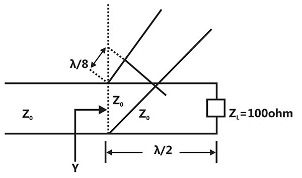
Sign in to see the solution
Log in to view the explanation, track your attempts, and keep your progress.
Sign in to UnlockIn an impedance smith chart, a clockwise moment along a constant resistance circle gives rise to
Sign in to see the solution
Log in to view the explanation, track your attempts, and keep your progress.
Sign in to UnlockThe magnitudes of the open-circuit and short-circuit input impedances of a transmission line are and respectively. The characteristic impedance of the line is,
Sign in to see the solution
Log in to view the explanation, track your attempts, and keep your progress.
Sign in to UnlockTwo coaxial cables 1 and 2 are filled with different dielectric constants and respectively. The ratio of the wavelengths in the two cables, is







Sign in to see the solution
Log in to view the explanation, track your attempts, and keep your progress.
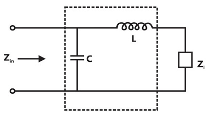
Sign in to UnlockDesign a lossless impedance matching network shown in Figure to transform to . Find the values of L, C and quality factor (Q) of the circuit at .



Sign in to see the solution
Log in to view the explanation, track your attempts, and keep your progress.
Sign in to UnlockAssuming perfect conductors of a transmission line, pure TEM propagation is NOT possible in
Sign in to see the solution
Log in to view the explanation, track your attempts, and keep your progress.
Sign in to UnlockIn a twin-wire transmission line in air, the adjacent voltage maxima are at 12.5 cm and 27.5 cm.
The operating frequency is
Sign in to see the solution
Log in to view the explanation, track your attempts, and keep your progress.
Sign in to UnlockIn air, a lossless transmission line of length 50 cm with , is operated at 25MHz. Its electrical path length is


0.5 meters
meters

radians

180 degrees
Sign in to see the solution
Log in to view the explanation, track your attempts, and keep your progress.
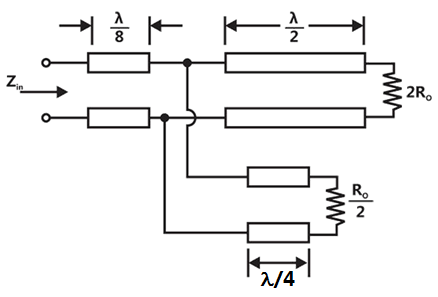
Sign in to UnlockAll transmission line sections shown in Figure have characteristic impedance. The input impedance equals






Sign in to see the solution
Log in to view the explanation, track your attempts, and keep your progress.
Sign in to UnlockA transmission line of characteristic impedance is terminated with a resistance. The minimum impedance measured on the line is equal to



Sign in to see the solution
Log in to view the explanation, track your attempts, and keep your progress.
Sign in to UnlockA very lossy, long, transmission line is open circuited at the load end. The input impedance measured at the other end of the line is approximately

0

None of the above
Sign in to see the solution
Log in to view the explanation, track your attempts, and keep your progress.
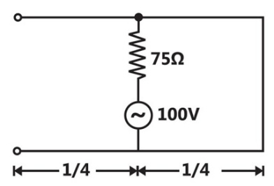
Sign in to Unlocksection of a transmission line, short circuited at one end and open circuited at the other end, is shown in the figure is generator is connected at the midpoint of the section as shown in the figure. Find voltage magnitude at the open circuited end of the line.



Sign in to see the solution
Log in to view the explanation, track your attempts, and keep your progress.
Sign in to UnlockThe capacitance per unit length and the characteristic impedance of a lossless transmission line are C and respectively. The velocity of a travelling wave on the transmission line is




Sign in to see the solution
Log in to view the explanation, track your attempts, and keep your progress.
Sign in to UnlockA load impedance is to be matched to a lossless transmission line by using a quarter wave line transformer (QWT). The characteristic impedance of the QWT required is ____

Sign in to see the solution
Log in to view the explanation, track your attempts, and keep your progress.
Sign in to UnlockIf a pure resistance load, when connected to a lossless 75-ohm line, produces a VSWR of 3 on the line, then the load impedance can only be 25 ohms. (True=1,False=0)
Sign in to see the solution
Log in to view the explanation, track your attempts, and keep your progress.
Sign in to UnlockConsider a transmission line of characteristic impedance of 50 ohm. Let it be terminated at one end by +j50 ohm. The VSWR produced by it in the transmission line will be
+1
0
+j
Sign in to see the solution
Log in to view the explanation, track your attempts, and keep your progress.
Sign in to UnlockA transmission line whose characteristic impedance is a pure resistance
Sign in to see the solution
Log in to view the explanation, track your attempts, and keep your progress.
Sign in to UnlockThe input impedance of a short-circuited lossless transmission line quarter wave length is
Sign in to see the solution
Log in to view the explanation, track your attempts, and keep your progress.
Sign in to Unlock