Network Analysis
Network Basics
Practice questions from Network Basics.
56
Total0
Attempted0
Correct0
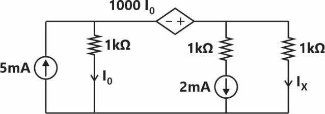
IncorrectIn the given circuit, the current (in mA) is _________.

Sign in to see the solution
Log in to view the explanation, track your attempts, and keep your progress.
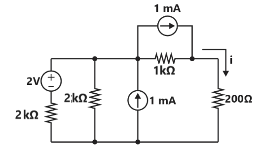
Sign in to UnlockIn the circuit shown below, the current I flowing through 200 Ω resistor is ________ mA.
(rounded off to two decimal places).
Sign in to see the solution
Log in to view the explanation, track your attempts, and keep your progress.
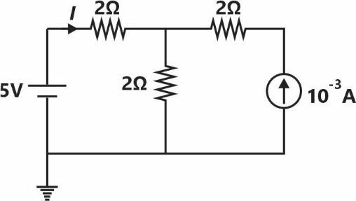
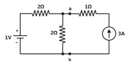
Sign in to UnlockThe current I in the circuit shown is ________.


Sign in to see the solution
Log in to view the explanation, track your attempts, and keep your progress.
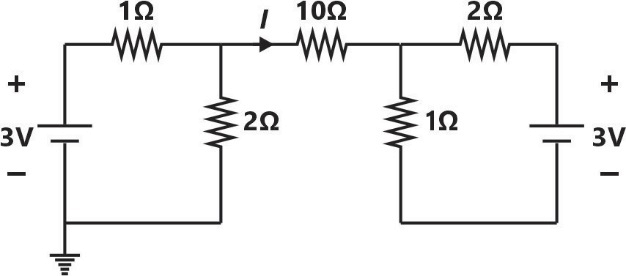
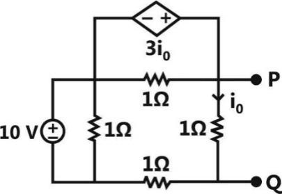
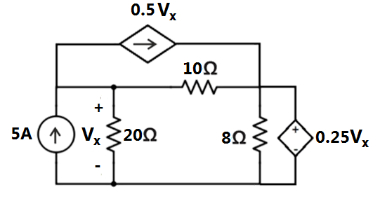
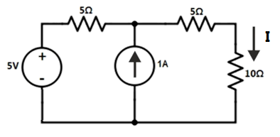
Sign in to UnlockConsider the circuit shown in the figure. The current I flowing through the 10Ω resistor is ________.
Sign in to see the solution
Log in to view the explanation, track your attempts, and keep your progress.
Sign in to UnlockConsider the circuit shown in the figure.
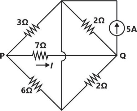
The current I flowing through the 7Ω resistor between P and Q (rounded off to one decimal place) is ________ A.
Sign in to see the solution
Log in to view the explanation, track your attempts, and keep your progress.
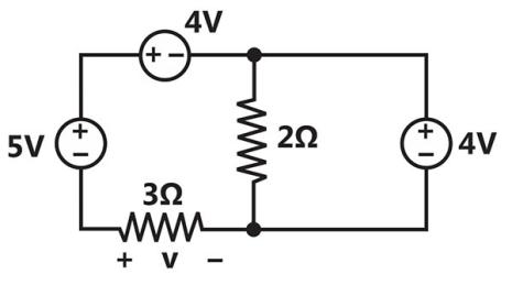
Sign in to UnlockConsider the circuit shown in the figure.
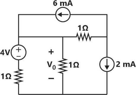
The value of (rounded off to one decimal place) is ________ V.

Sign in to see the solution
Log in to view the explanation, track your attempts, and keep your progress.
Sign in to UnlockConsider the network shown below with,and . The network is connected to a constant voltage source of 11V.


The magnitude of the current (in amperes. accurate
to two decimal places) through the source is _______
Sign in to see the solution
Log in to view the explanation, track your attempts, and keep your progress.
Sign in to UnlockA connection is made consisting of resistance A in series with a parallel combination of resistances B and C. Three resistors of value are provided. Consider all possible permutations of the given resistors into the positions A, B, C, and identify the configurations with maximum possible overall resistance, and also the ones with minimum possible overall resistance. The ratio of maximum to minimum values of the resistances (up to second decimal place) is ______________.

Sign in to see the solution
Log in to view the explanation, track your attempts, and keep your progress.
Sign in to UnlockConsider the circuit shown in the figure.
The Thevenin equivalent resistance across P-Q is _______________.[

Sign in to see the solution
Log in to view the explanation, track your attempts, and keep your progress.
Sign in to UnlockIn the given circuit, each resistor has a value equal to 1Ω.
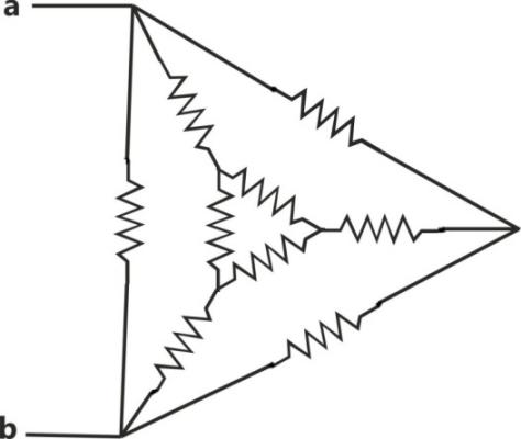
What is the equivalent resistance across the terminals a and b?
Sign in to see the solution
Log in to view the explanation, track your attempts, and keep your progress.
Sign in to UnlockIn the circuit shown in the figure, the magnitude of the current (in amperes) through is _______.

Sign in to see the solution
Log in to view the explanation, track your attempts, and keep your progress.
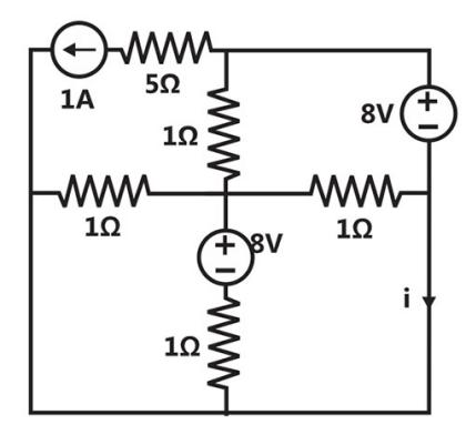
Sign in to UnlockIn the figure shown, the current i (in ampere) is ____.
Sign in to see the solution
Log in to view the explanation, track your attempts, and keep your progress.
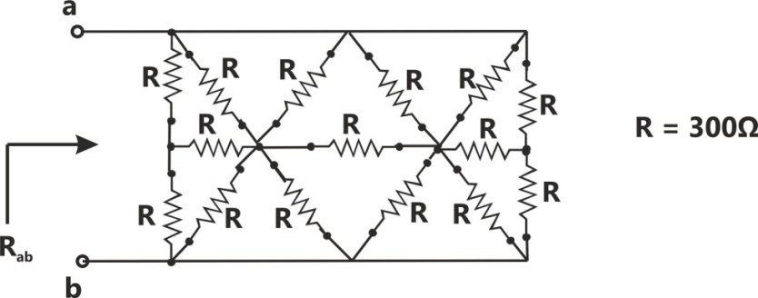
Sign in to UnlockIn the network shown in the figure, all resistors are identical with R = 300 Ω. The resistance (in Ω) of the network is ______.

Sign in to see the solution
Log in to view the explanation, track your attempts, and keep your progress.
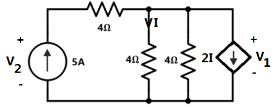
Sign in to UnlockIn the given circuit, the values of and respectively are


Sign in to see the solution
Log in to view the explanation, track your attempts, and keep your progress.
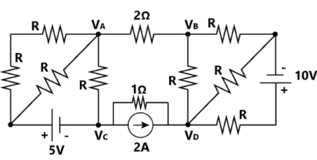
Sign in to UnlockIn the circuit shown, the voltage (in Volts) is ___________.

Sign in to see the solution
Log in to view the explanation, track your attempts, and keep your progress.
Sign in to UnlockConsider the following figure
The current in the resistor in Amps is

Sign in to see the solution
Log in to view the explanation, track your attempts, and keep your progress.
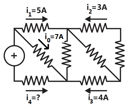
Sign in to UnlockConsider the configuration shown in the figure which is a portion of a larger electrical network
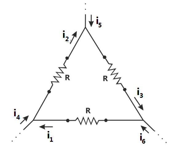
For and currents, , , which of the following is TRUE


Data is sufficient to conclude that the supposed currents are impossible

Sign in to see the solution
Log in to view the explanation, track your attempts, and keep your progress.
Sign in to UnlockA Y-network has resistances of 10Ω each in two of its arms, while the third arm has a resistance of 11Ω. In the equivalent -network, the lowest value (in Ω) among the three resistances is ________.

Sign in to see the solution
Log in to view the explanation, track your attempts, and keep your progress.
Sign in to UnlockA periodic variable x is shown in the figure as a function of time. The root-mean-square (rms) value of x is _________.
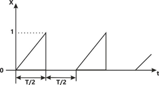
Sign in to see the solution
Log in to view the explanation, track your attempts, and keep your progress.
Sign in to UnlockIn the figure shown, the value of the current I (in Amperes) is__________.
Sign in to see the solution
Log in to view the explanation, track your attempts, and keep your progress.
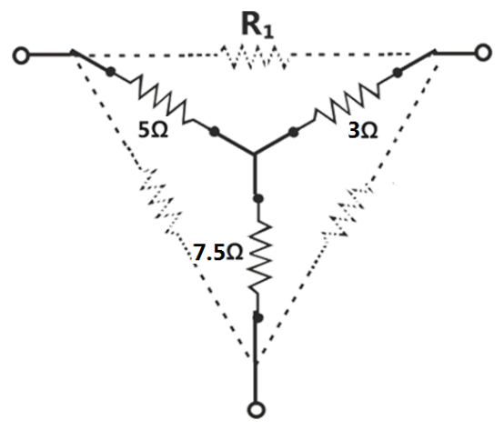
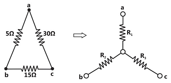
Sign in to UnlockFor the Y-network shown in the figure, the value of R1 (in Ω) in the equivalent ∆-network is ____.
Sign in to see the solution
Log in to view the explanation, track your attempts, and keep your progress.
Sign in to UnlockThe circuit shown in the figure represents a
Sign in to see the solution
Log in to view the explanation, track your attempts, and keep your progress.
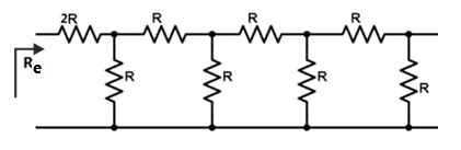
Sign in to UnlockThe equivalent resistance in the infinite ladder network shown in the figure, is . The value of /R is ________.

Sign in to see the solution
Log in to view the explanation, track your attempts, and keep your progress.
Sign in to UnlockConsider a delta connection of resistors and its equivalent star connection as shown below. If all elements of the delta connection are scaled by a factor, , the elements of the corresponding star equivalent will be scaled by a factor of


Sign in to see the solution
Log in to view the explanation, track your attempts, and keep your progress.
Sign in to UnlockThe following arrangement consists of an ideal transformer and an attenuator which attenuates by a factor of 0.8. An ac voltage is applied across WX to get an open circuit voltage across YZ. Next, an ac voltage is applied across YZ to get an open circuit voltage across WX. Then, , are respectively,


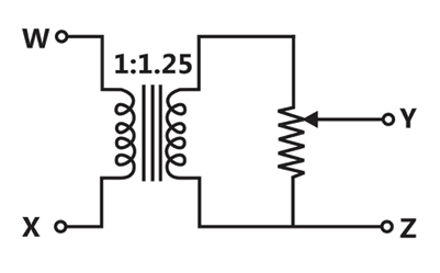
and


and

and
and
Sign in to see the solution
Log in to view the explanation, track your attempts, and keep your progress.
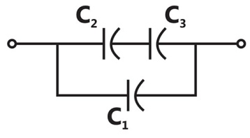
Sign in to UnlockThree capacitors , and whose values are , and respectively, have breakdown voltages of 10V, 5V and 2V respectively. For the interconnection shown below, the maximum safe voltage in Volts that can be applied across the combination, and the corresponding total charge in stored in the effective capacitance across the terminals are respectively,


Sign in to see the solution
Log in to view the explanation, track your attempts, and keep your progress.
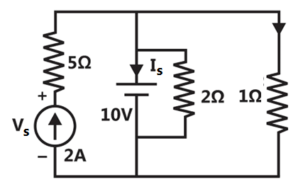
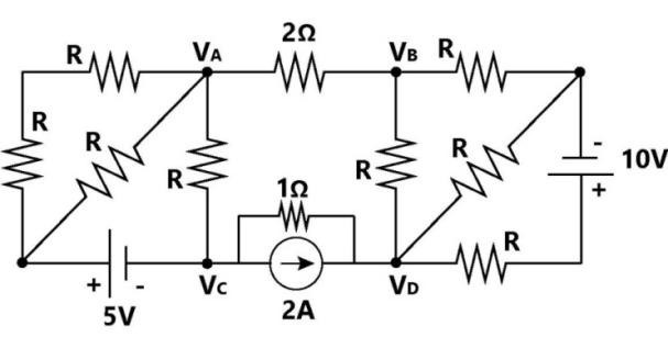
Sign in to UnlockConsider the following figure
The current in Amps in the voltage source and voltage in Volts across the current source respectively, are


Sign in to see the solution
Log in to view the explanation, track your attempts, and keep your progress.
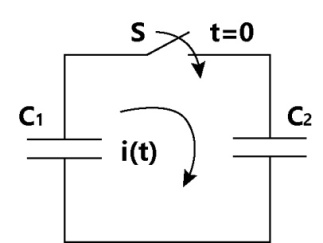
Sign in to UnlockIn the following figure, and are ideal capacitors. has been charged to 12V before the ideal switch S is closed at t = 0. The current i(t) for all t is


Sign in to see the solution
Log in to view the explanation, track your attempts, and keep your progress.
Sign in to UnlockIf V, then is


Sign in to see the solution
Log in to view the explanation, track your attempts, and keep your progress.
Sign in to UnlockIn the circuit shown, the power supplied by the voltage source is
Sign in to see the solution
Log in to view the explanation, track your attempts, and keep your progress.
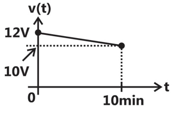
Sign in to UnlockA fully charged mobile phone with a 12 V battery is good for a 10 minute talk-time. Assume that, during the talk-time, the battery delivers a constant current of 2 A and its voltage drops linearly from 12 V to 10 V as shown in the figure. How much energy does the battery deliver during this talk-time?
Sign in to see the solution
Log in to view the explanation, track your attempts, and keep your progress.
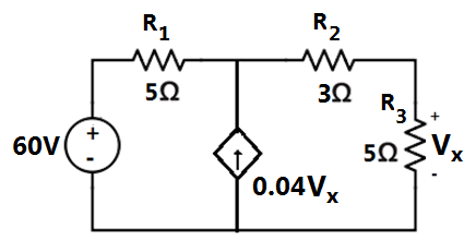
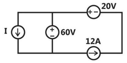
Sign in to UnlockIn the interconnection of ideal sources shown in the figure, it is known that the 60 V source is absorbing power. Which of the following can be the value of the current source I?
Sign in to see the solution
Log in to view the explanation, track your attempts, and keep your progress.
Sign in to Unlockf and in the bridge Circuit shown in figure, then the reading in the ideal Voltmeter connected between a and b is


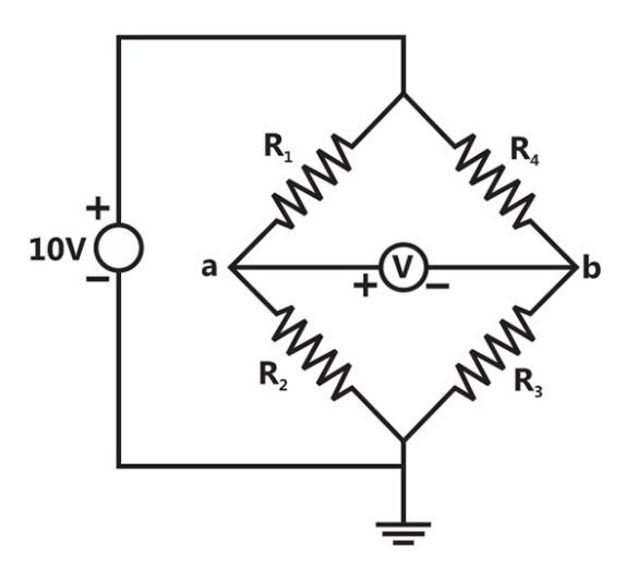
Sign in to see the solution
Log in to view the explanation, track your attempts, and keep your progress.
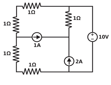
Sign in to UnlockThe minimum number of equations required to analyse the circuit shown in Figure is
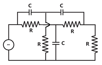
Sign in to see the solution
Log in to view the explanation, track your attempts, and keep your progress.
Sign in to UnlockTwelve 1Ω resistances are used as edges to form a cube. The resistance between two diagonally opposite corners of the cube is


Sign in to see the solution
Log in to view the explanation, track your attempts, and keep your progress.
Sign in to UnlockThe current flowing through the resistance R in the circuit in figure has the form P cos 4t, where P is
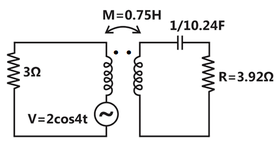
Sign in to see the solution
Log in to view the explanation, track your attempts, and keep your progress.
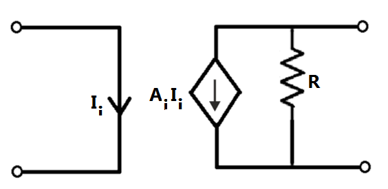
Sign in to UnlockThe dependent current source shown in Figure
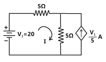
Sign in to see the solution
Log in to view the explanation, track your attempts, and keep your progress.
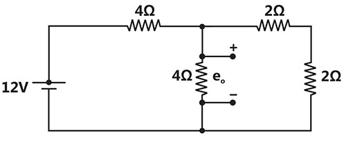
Sign in to UnlockThe voltage e₀ in figure is
Sign in to see the solution
Log in to view the explanation, track your attempts, and keep your progress.
Sign in to UnlockIf each branch of a Delta circuit has impedance, then each branch of the equivalent Wye circuit has impedance.


3Z


Sign in to see the solution
Log in to view the explanation, track your attempts, and keep your progress.
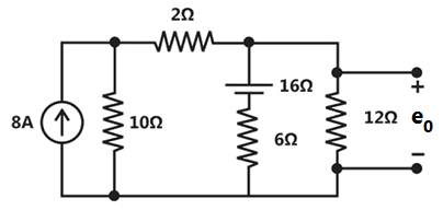
Sign in to UnlockThe voltage in figure is

Sign in to see the solution
Log in to view the explanation, track your attempts, and keep your progress.
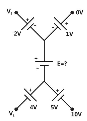
Sign in to UnlockIn the circuit of Figure, the value of the voltage source E is
Sign in to see the solution
Log in to view the explanation, track your attempts, and keep your progress.
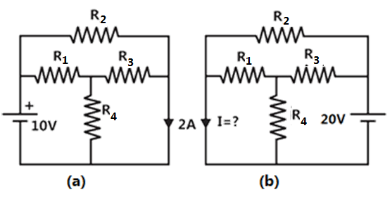
Sign in to UnlockUse the data of Figure (a). The current I in the circuit of Figure (b) is
Sign in to see the solution
Log in to view the explanation, track your attempts, and keep your progress.
Sign in to UnlockDelta-connected network with its Wye-equivalent is shown in Figure. The resistance, and (in ohms) are respectively


Sign in to see the solution
Log in to view the explanation, track your attempts, and keep your progress.
Sign in to UnlockThe nodal method of circuit analysis is based on
Sign in to see the solution
Log in to view the explanation, track your attempts, and keep your progress.
Sign in to UnlockThe voltage across the terminals a and b in Figure is
Sign in to see the solution
Log in to view the explanation, track your attempts, and keep your progress.
Sign in to UnlockThe current in the circuit of the figure is equal to

Sign in to see the solution
Log in to view the explanation, track your attempts, and keep your progress.
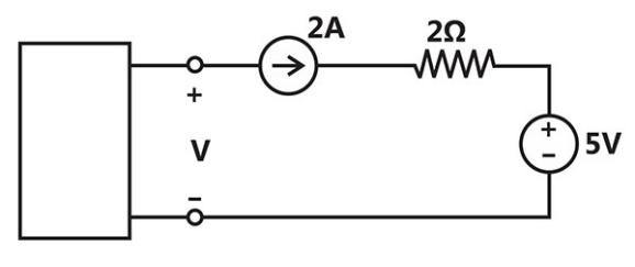
Sign in to UnlockThe voltage V in the figure is equal to
Sign in to see the solution
Log in to view the explanation, track your attempts, and keep your progress.
Sign in to UnlockThe voltage V in the figure is always equal to
Sign in to see the solution
Log in to view the explanation, track your attempts, and keep your progress.
Sign in to UnlockThe voltage V in the figure is
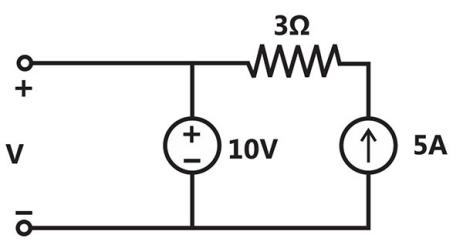
Sign in to see the solution
Log in to view the explanation, track your attempts, and keep your progress.
Sign in to Unlock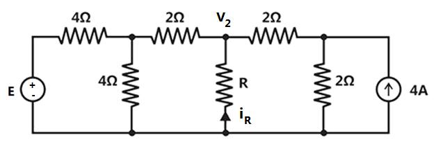
In the circuit of figure when , the current equals to 10 A


Value of R for which it absorbs maximum power = 2 Ohm
Value of E = -96


Sign in to see the solution
Log in to view the explanation, track your attempts, and keep your progress.
Sign in to UnlockThe RMS value of a rectangular wave of period T, having a value of + V for a duration, and –V for the duration, , equals


V


Sign in to see the solution
Log in to view the explanation, track your attempts, and keep your progress.
Sign in to UnlockA dc circuit shown in figure has a voltage source V, a current source I and several resistors. A particular resistor R dissipates a power of 4 watts when V alone is active. The same resistor R dissipates a power of 9 watts when I alone is active. The power dissipated by R when both sources are active will be
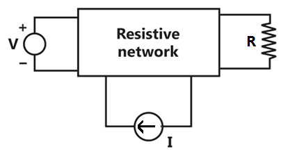
Sign in to see the solution
Log in to view the explanation, track your attempts, and keep your progress.
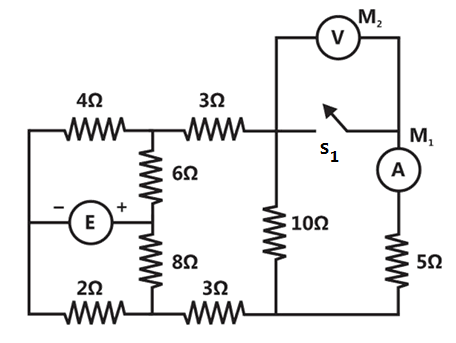
Sign in to UnlockIn the circuit of figure, when switch is closed, the ideal ammeter reads 5A. What will be ideal voltmeter read when is kept open? (The value of E is not specified).


Sign in to see the solution
Log in to view the explanation, track your attempts, and keep your progress.
Sign in to UnlockA network contains linear resistors and ideal voltage sources. If values of all the resistors are doubled, then the voltage across each resistor is
Sign in to see the solution
Log in to view the explanation, track your attempts, and keep your progress.
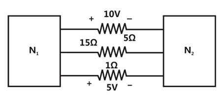
Sign in to UnlockThe two electrical sub network and are connected through three resistors as shown in figure. The voltage across 5 ohm resistor and 1 ohm resistor are given to be 10 V and 5V, respectively. Then voltage across 15 ohm resistor is


Sign in to see the solution
Log in to view the explanation, track your attempts, and keep your progress.
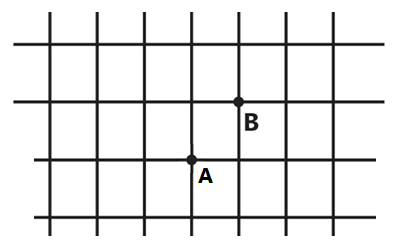
Sign in to UnlockAn infinite grid is built up by connecting resistors in the manner indicated in figure, where each branch represents one ohm resistor. Calculate the effective resistance between the nodes A and B.
Sign in to see the solution
Log in to view the explanation, track your attempts, and keep your progress.
Sign in to Unlock