Analog Electronics
Oscillators
Practice questions from Oscillators.
22
Total0
Attempted0
Correct0
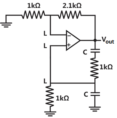
IncorrectIn the circuit below, the opamp is ideal
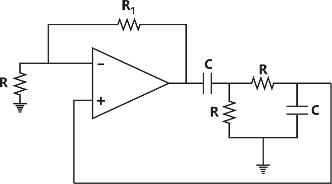
If the circuit is to show sustained oscillations, the respective values of and the corresponding frequency of oscillation are________.

and


and


and
and

Sign in to see the solution
Log in to view the explanation, track your attempts, and keep your progress.
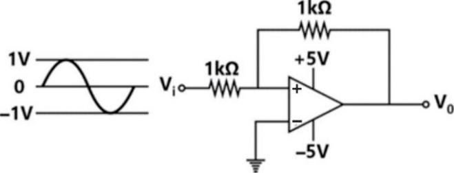
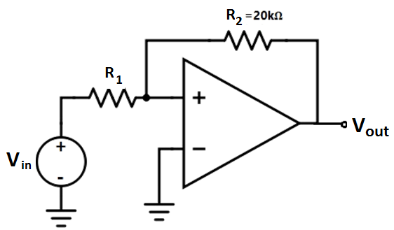
Sign in to UnlockThe components in the circuit shown below are ideal. If the op-amp is in positive feedback and the input voltage is a sine wave of amplitude 1V, the output voltage is [


Sign in to see the solution
Log in to view the explanation, track your attempts, and keep your progress.
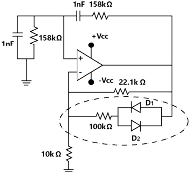
Sign in to UnlockConsider the oscillator circuit shown in the figure. The function of the network (shown in dotted lines) consisting of the 100kΩ resistor in series with the two diodes connected back-to-back is to:
Sign in to see the solution
Log in to view the explanation, track your attempts, and keep your progress.
Sign in to UnlockIn the op-amp circuit shown, the Zener diodes
and clamp the output voltage to +5 V or −5 V. The switch S is initially closed and is opened at time.


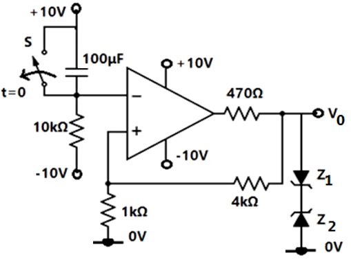
The time (in seconds) at which changes state is ____.


Sign in to see the solution
Log in to view the explanation, track your attempts, and keep your progress.
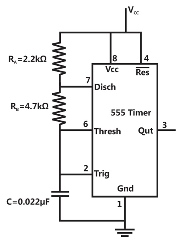
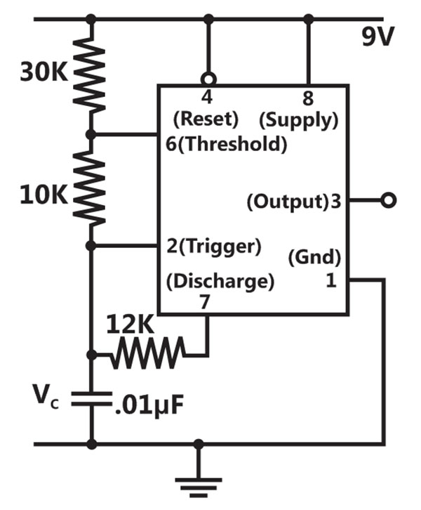
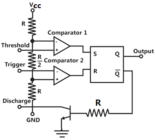
Sign in to UnlockIn the Astable multivibrator circuit shown in the figure, the frequency of oscillation (in kHz) at the output pin 3 is _________.
Sign in to see the solution
Log in to view the explanation, track your attempts, and keep your progress.
Sign in to UnlockIn the bi-stable circuit shown, the ideal op-amp has saturation levels of ± 5 V. The value of (in kΩ) that gives a hysteresis width of 500 mV is ________.

Sign in to see the solution
Log in to view the explanation, track your attempts, and keep your progress.
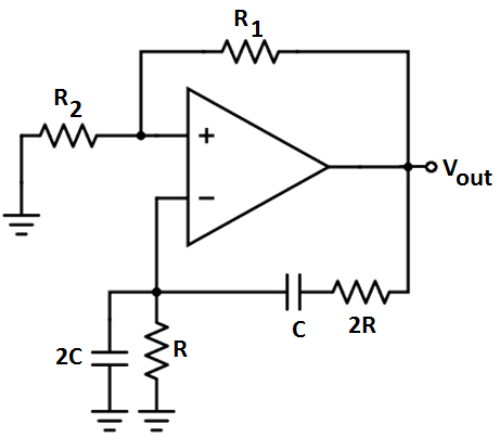
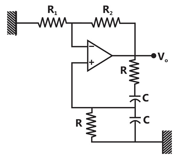
Sign in to UnlockThe circuit shown in the figure has an ideal op-amp. The oscillation frequency and the condition to sustain the oscillations, respectively, are
and


and

and

and
Sign in to see the solution
Log in to view the explanation, track your attempts, and keep your progress.
Sign in to UnlockIn the following Astable multi-vibrator circuit, which properties of depend on ?


Sign in to see the solution
Log in to view the explanation, track your attempts, and keep your progress.
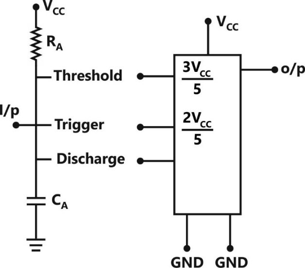
Sign in to UnlockAn Astable multivibrator circuit using IC 555 timer is shown below. Assume that the circuit is oscillating steadily. The voltage across the capacitor varies between

Sign in to see the solution
Log in to view the explanation, track your attempts, and keep your progress.
Sign in to UnlockConsider the Schmidt trigger circuit shown below.
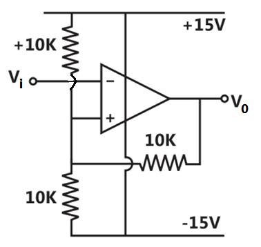
A triangular wave which goes from -12V to 12V is applied to the inverting input of the OPAMP. Assume that the output of the OPAMP swings from +15V to -15V. The voltage at the non-inverting input switches between
Sign in to see the solution
Log in to view the explanation, track your attempts, and keep your progress.
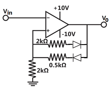
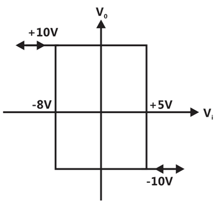
Sign in to UnlockGiven the ideal operational amplifier circuit shown in figure indicate the correct transfer characteristics assuming ideal diodes with zero cut-in voltage.
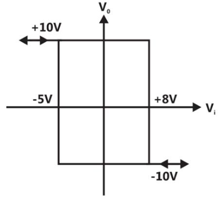
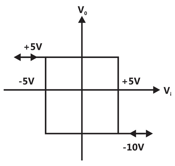
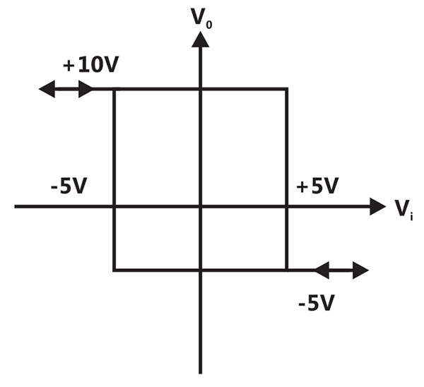
Sign in to see the solution
Log in to view the explanation, track your attempts, and keep your progress.
Sign in to UnlockThe value of C required for sinusoidal oscillations of frequency 1 kHz in the circuit of figure is


Sign in to see the solution
Log in to view the explanation, track your attempts, and keep your progress.
Sign in to UnlockThe oscillator circuit shown in figure has an ideal inverting amplifier. Its frequency of oscillation (in Hz) is
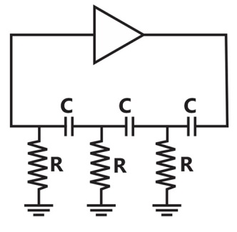


Sign in to see the solution
Log in to view the explanation, track your attempts, and keep your progress.
Sign in to UnlockThe circuit in Figure employs positive feedback and is intended to generate sinusoidal oscillation. If at a frequency, then to sustain oscillation at this frequency

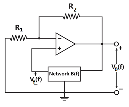


Sign in to see the solution
Log in to view the explanation, track your attempts, and keep your progress.
Sign in to UnlockThe oscillator circuit shown in figure is
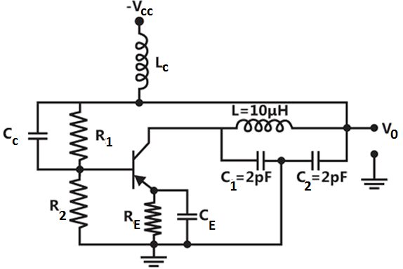
Hartley oscillator with

colpitts oscillator with

Hartley oscillator with

colpitts oscillator with
Sign in to see the solution
Log in to view the explanation, track your attempts, and keep your progress.
Sign in to UnlockThe configuration of Figure is a
Sign in to see the solution
Log in to view the explanation, track your attempts, and keep your progress.
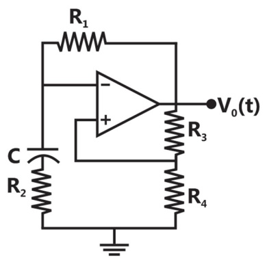
Sign in to UnlockFind the value of R’ in the circuit of Figure, for the generating sinusoidal oscillations. Find the frequency of oscillations.
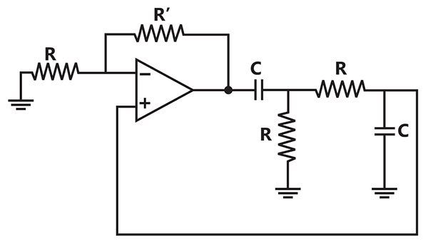
R’ = 4R
R’ = 2R


Sign in to see the solution
Log in to view the explanation, track your attempts, and keep your progress.
Sign in to UnlockImplement a mono-stable multi-vibrator using the timer circuit shown in the figure. Also, determine an expression for ON time T of the output pulse.


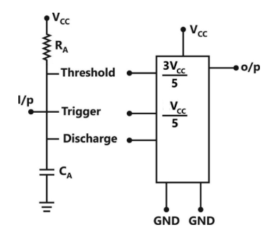
Sign in to see the solution
Log in to view the explanation, track your attempts, and keep your progress.
Sign in to UnlockAn IC 555 chip has been used to construct a pulse-Generator. Typical pin a connection with components is shown below in the figure is for such an application. However it is desired to generate a square pulse of 10 kHz.
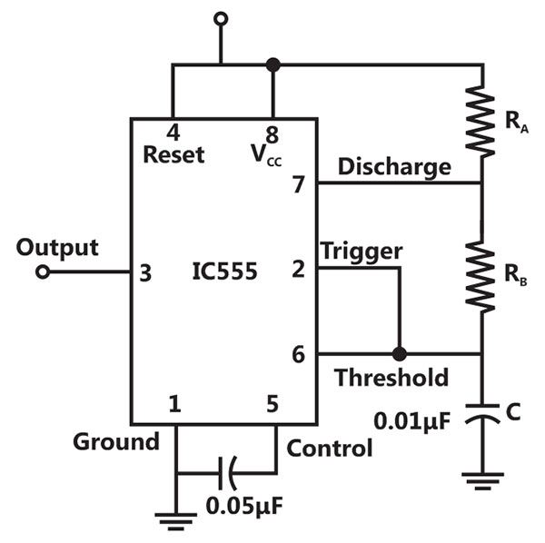
Evaluate values of and if the capacitor C has the value of 0.01µF for the configuration modification in the external circuit configuration.


Sign in to see the solution
Log in to view the explanation, track your attempts, and keep your progress.
Sign in to UnlockThe figure is shows the block diagram of phase-locked-loop (PLL) in the locked condition.
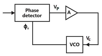
The output voltage of the phase detector is given by
,

Where = phase of the input signal, and

= the phase of the output voltage Controlled Oscillator (VCO).

The value of is 1 volt/radian,

The frequency deviation of the VCO output is,

Where = input voltage of the VCO, and
= 159.15 Hz/volt

The amplifier A is a buffer with a voltage gain of unity.
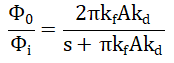
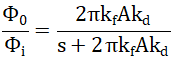
(a) Derive the transfer function.

(b) Let the loop to be locked for time and radian, where u(t) is the unit step function. Determine for.


Sign in to see the solution
Log in to view the explanation, track your attempts, and keep your progress.
Sign in to UnlockValue of R in the oscillator circuit shown in the given figure, so chosen that it just oscillates at an angular frequency of . The value of and the required value of R will respectively be

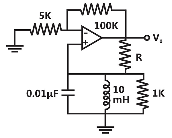
rad/sec,


rad/sec,

rad/sec,

rad/sec,
Sign in to see the solution
Log in to view the explanation, track your attempts, and keep your progress.
Sign in to UnlockAn RC-coupled amplifier is assumed to have a single-pole low frequency transfer function. The maximum lower cut-off frequency allowed for the amplifier to pass 50 Hz square wave with no more than 10% tilt is ____________.
Sign in to see the solution
Log in to view the explanation, track your attempts, and keep your progress.
Sign in to Unlock