Network Analysis
Network Theorems - DC Circuits
Practice questions from Network Theorems - DC Circuits.
22
Total0
Attempted0
Correct0
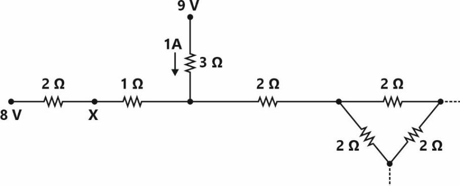
IncorrectConsider a part of an electrical network as shown below. Some node voltages, and the current flowing through the resistor are as indicated.

The voltage (in Volts) at node is ________.





Sign in to see the solution
Log in to view the explanation, track your attempts, and keep your progress.
Sign in to UnlockIn the network shown below, maximum power is to be transferred to the load .

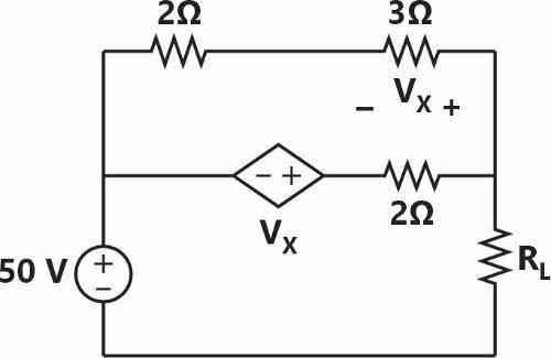
The value of in is __________.


Sign in to see the solution
Log in to view the explanation, track your attempts, and keep your progress.
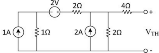
Sign in to UnlockIn the circuit shown below, the Thevenin voltage is

Sign in to see the solution
Log in to view the explanation, track your attempts, and keep your progress.
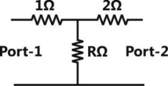
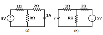
Sign in to UnlockConsider the two-port resistive network shown in the figure. When an excitation of 5 V is applied across Port 1, and Port 2 is shorted, the current through the short circuit at Port 2 is measured to be 1 A (see (a) in the figure). Now, if an excitation of 5V is applied across Port 2 and Port 1 is shorted (see (b) in the figure), what is the current through the short circuit at Port 1?
Sign in to see the solution
Log in to view the explanation, track your attempts, and keep your progress.
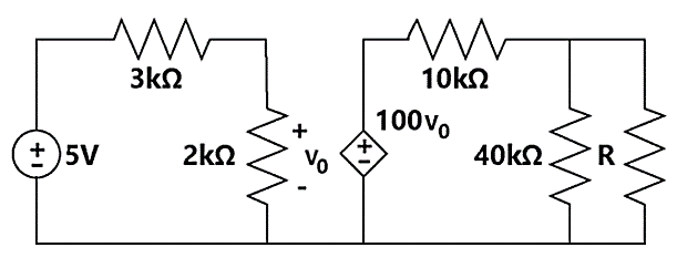
Sign in to UnlockIn the circuit shown in the figure, the maximum power (in watt) delivered to the resistor R is________.
Sign in to see the solution
Log in to view the explanation, track your attempts, and keep your progress.
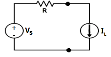
Sign in to UnlockIn the circuit shown below, is a constant voltage source and is a constant current load. The value of that maximizes the power absorbed by the constant current load is






Sign in to see the solution
Log in to view the explanation, track your attempts, and keep your progress.
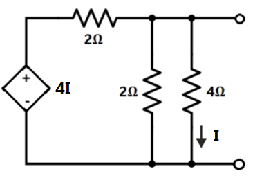
Sign in to UnlockIn the circuit shown, the Norton equivalent resistance (in Ω) across terminals a-b is _______.
Sign in to see the solution
Log in to view the explanation, track your attempts, and keep your progress.
Sign in to UnlockFor the circuit shown in the figure, the Thevenin’s equivalent voltage (in Volts) across terminals a-b is ________.
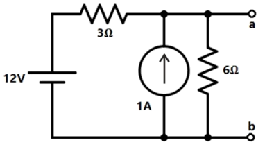
Sign in to see the solution
Log in to view the explanation, track your attempts, and keep your progress.
Sign in to UnlockNorton’s theorem states that a complex network connected to a load can be replaced with an equivalent impedance
Sign in to see the solution
Log in to view the explanation, track your attempts, and keep your progress.
Sign in to UnlockThe magnitude of current (in mA) through the resistor in the figure shown is_______.

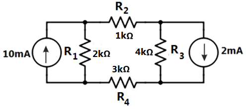
Sign in to see the solution
Log in to view the explanation, track your attempts, and keep your progress.
Sign in to UnlockThe impedance looking into nodes 1 and 2 in the given circuit is
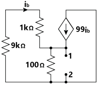
Sign in to see the solution
Log in to view the explanation, track your attempts, and keep your progress.
Sign in to UnlockAssuming both the voltage sources are in phase, the value of R for which maximum power is transferred from circuit A to circuit B is
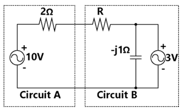
Sign in to see the solution
Log in to view the explanation, track your attempts, and keep your progress.
Sign in to UnlockIn the circuit shown below, the Norton equivalent current in amperes with respect to the terminals P and Q is
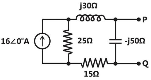
Sign in to see the solution
Log in to view the explanation, track your attempts, and keep your progress.
Sign in to UnlockIn the circuit shown below, the value of such that the power transferred to is maximum is

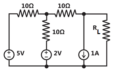




Sign in to see the solution
Log in to view the explanation, track your attempts, and keep your progress.
Sign in to UnlockIn the circuit shown, what value of maximizes the power delivered to?
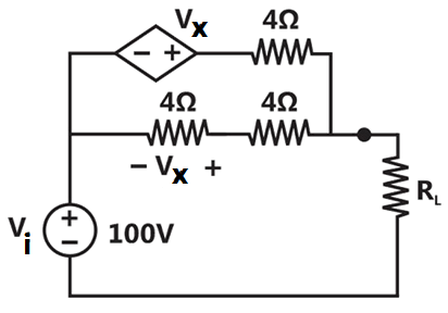




Sign in to see the solution
Log in to view the explanation, track your attempts, and keep your progress.
Sign in to UnlockFor the circuit shown in figure, Thevenin’s voltage and Thevenin’s equivalent resistance at terminals a – b is
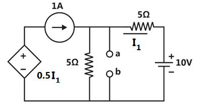
5 V and

7.5 V and

4 V and
3 V and
Sign in to see the solution
Log in to view the explanation, track your attempts, and keep your progress.
Sign in to UnlockFor the circuit shown in the figure, the Thevenin’s voltage and resistance looking into X-Y are
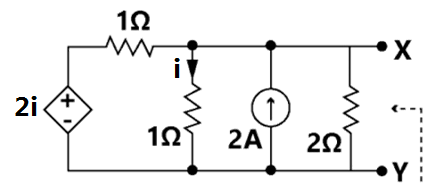
Sign in to see the solution
Log in to view the explanation, track your attempts, and keep your progress.
Sign in to UnlockThe maximum power that can be transferred to the load resistor from the voltage source in figure is

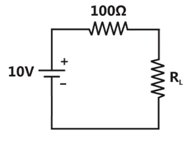
Sign in to see the solution
Log in to view the explanation, track your attempts, and keep your progress.
Sign in to UnlockIn the network of Figure, the maximum power is delivered to if its value is
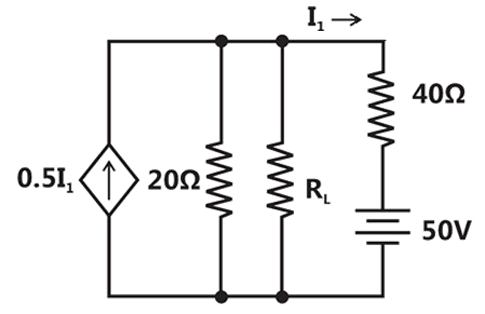
16Ω

60Ω
20Ω
Sign in to see the solution
Log in to view the explanation, track your attempts, and keep your progress.
Sign in to UnlockThe value of R (in ohms) required for maximum power transfer in the network shown in Figure is
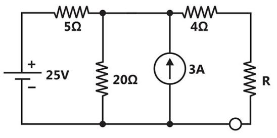
Sign in to see the solution
Log in to view the explanation, track your attempts, and keep your progress.
Sign in to UnlockSuperposition theorem is NOT applicable to networks containing
Sign in to see the solution
Log in to view the explanation, track your attempts, and keep your progress.
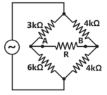
Sign in to UnlockThe value of the resistance, R, connected across the terminals, A and B, which will absorb the maximum power, is




Sign in to see the solution
Log in to view the explanation, track your attempts, and keep your progress.
Sign in to Unlock