Control Systems
State Variable Analysis
Practice questions from State Variable Analysis.
43
Total0
Attempted0
Correct0
IncorrectConsider a system where , and are three internal state signals and is the input signal. The differential equations governing the system are given by
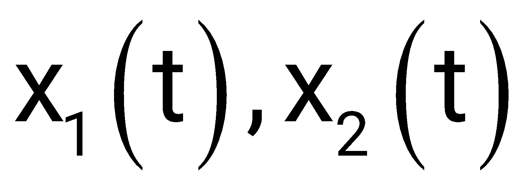
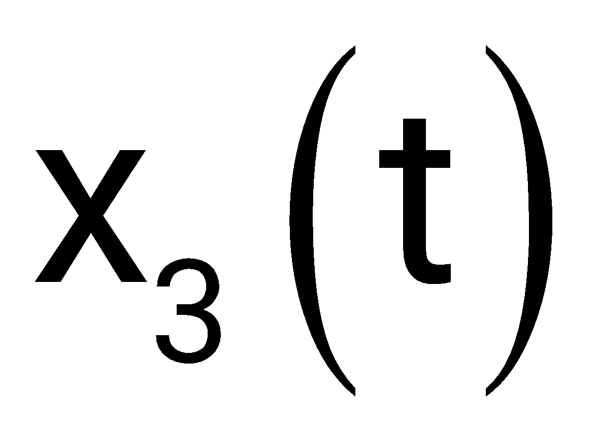
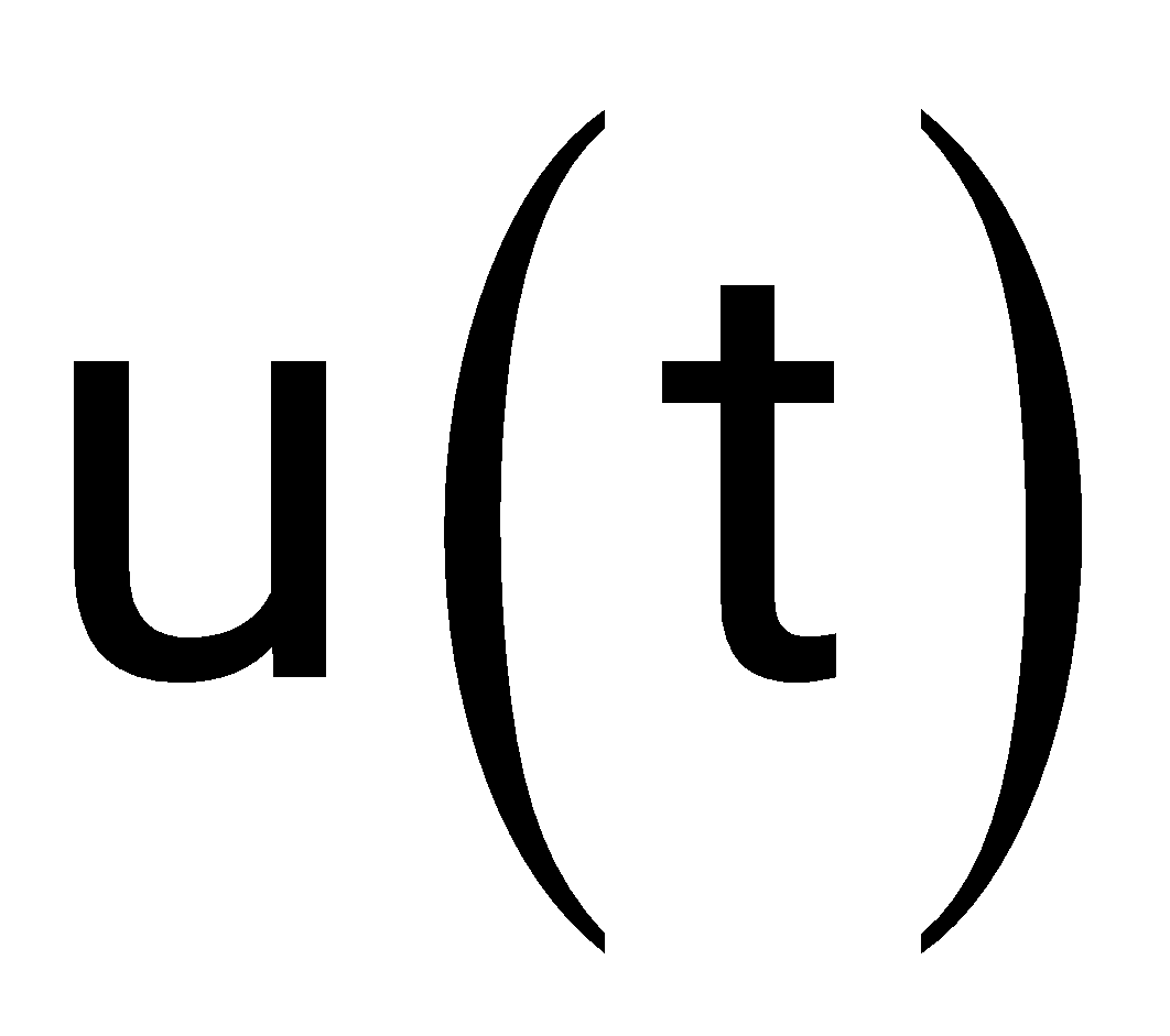
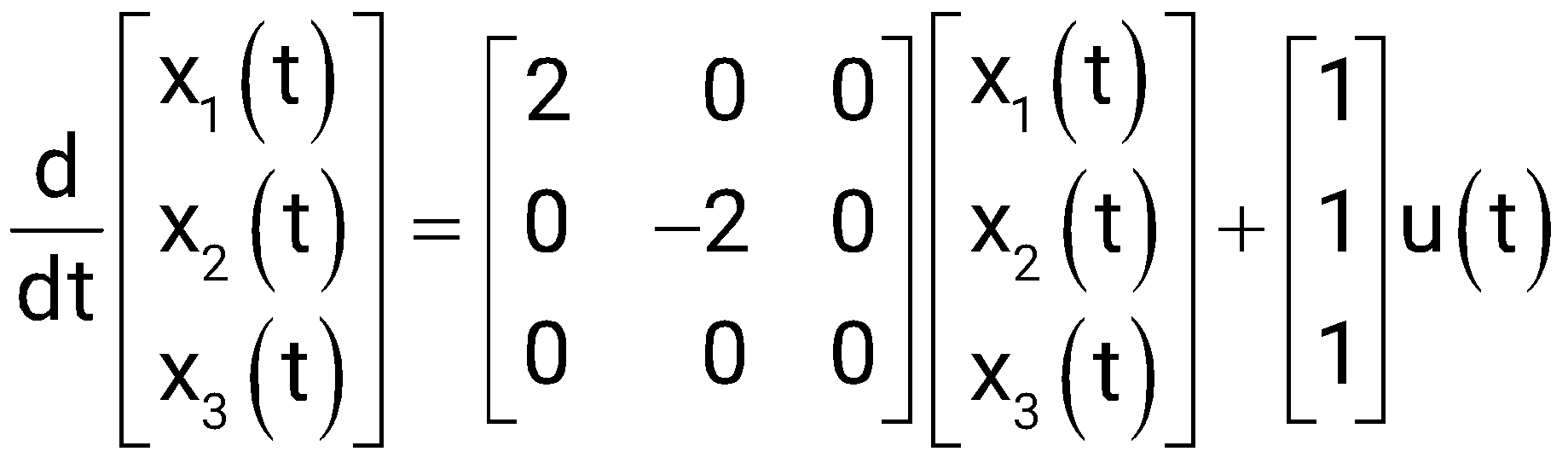
Which of the following statements is/are TRUE?
The signals , and are bounded for all bounded inputs
There exists a bounded input such that at least one of the signals , , and is unbounded
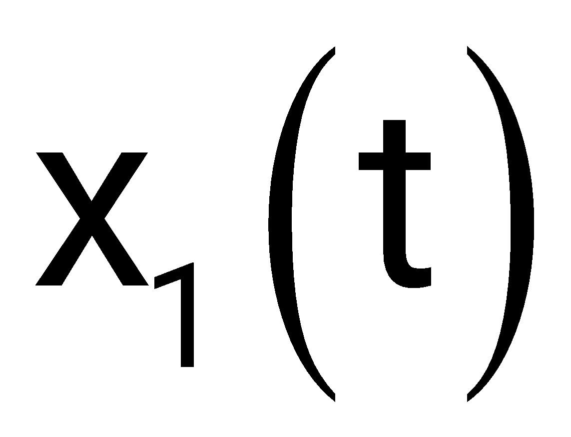
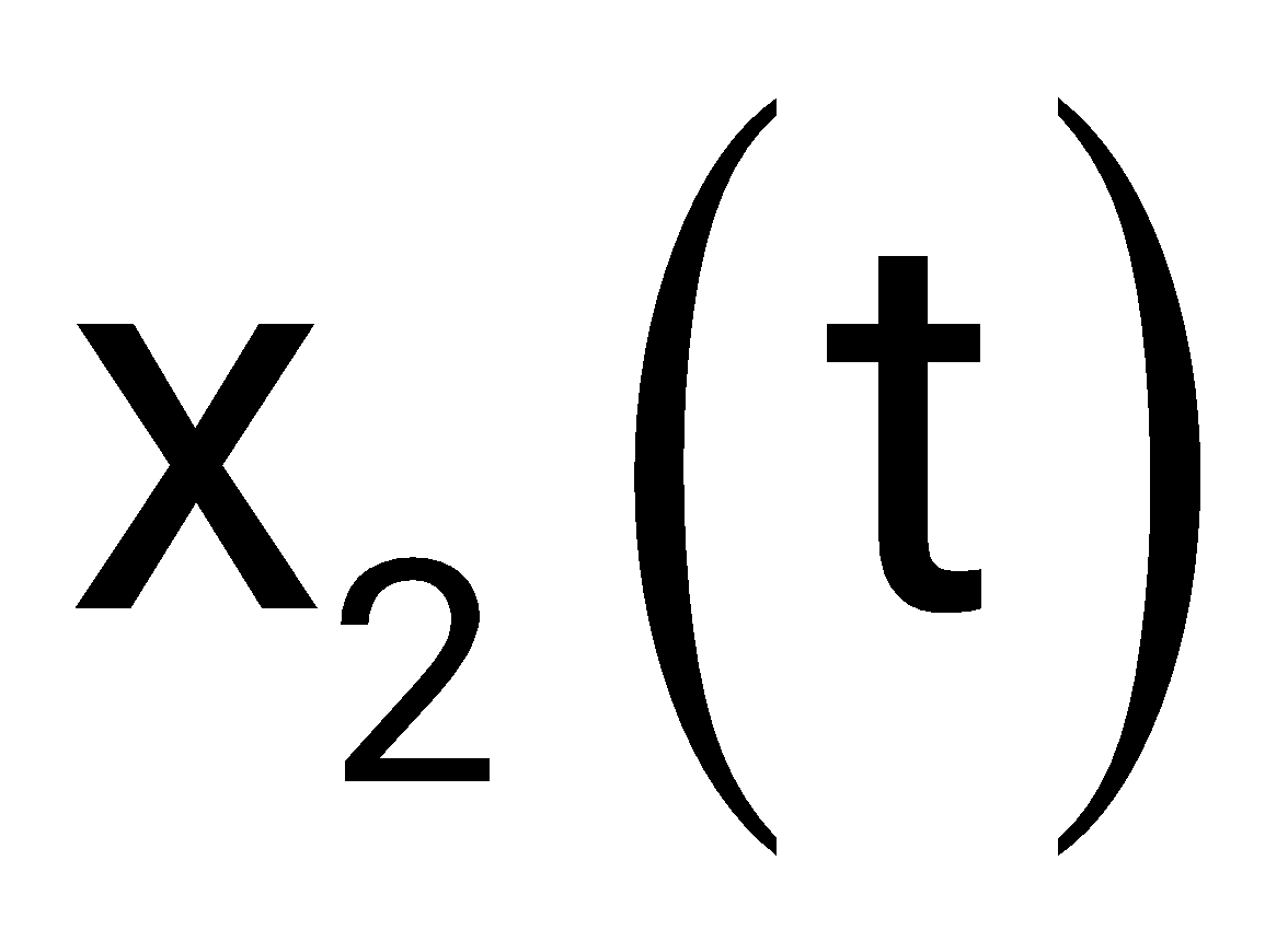
There exists a bounded input such that the signals , and are unbounded
The signals , and are unbounded for all bounded inputs
Sign in to see the solution
Log in to view the explanation, track your attempts, and keep your progress.
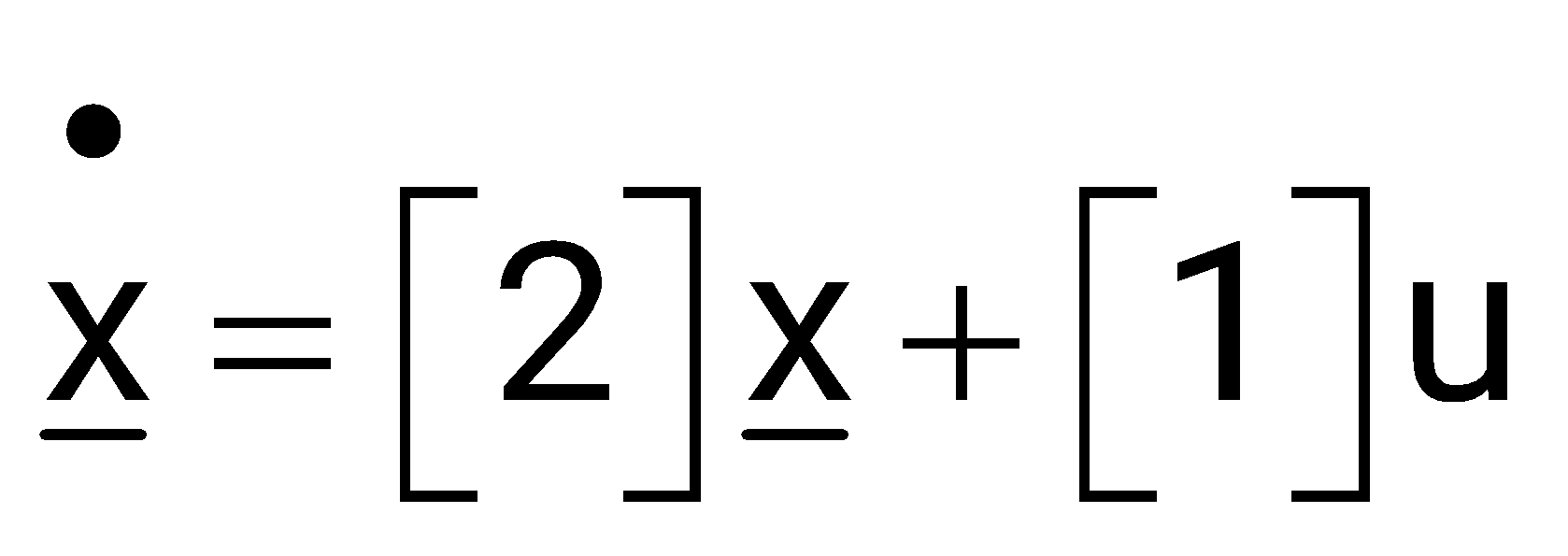
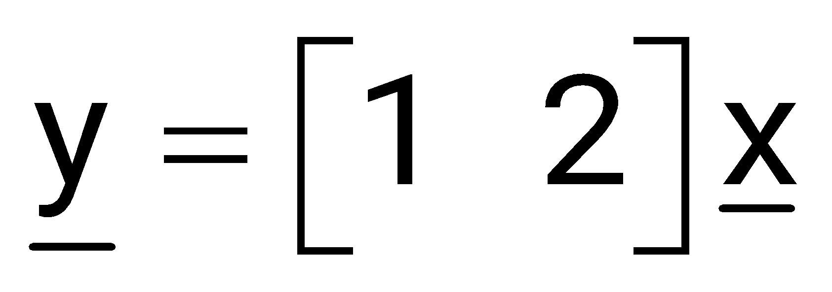
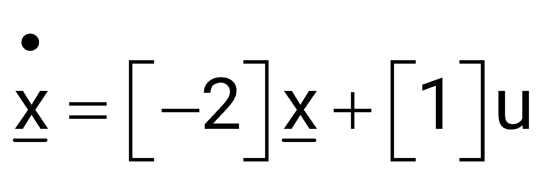
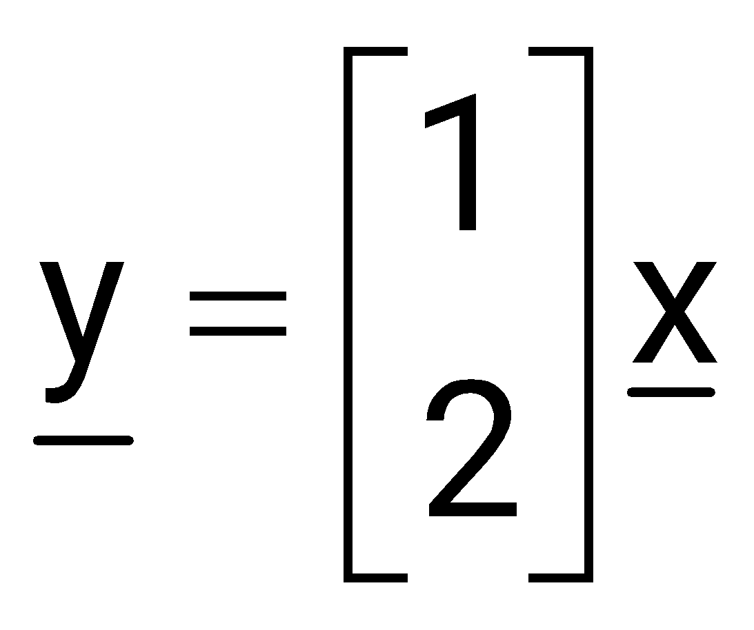
Sign in to UnlockConsider a system S represented in state space as
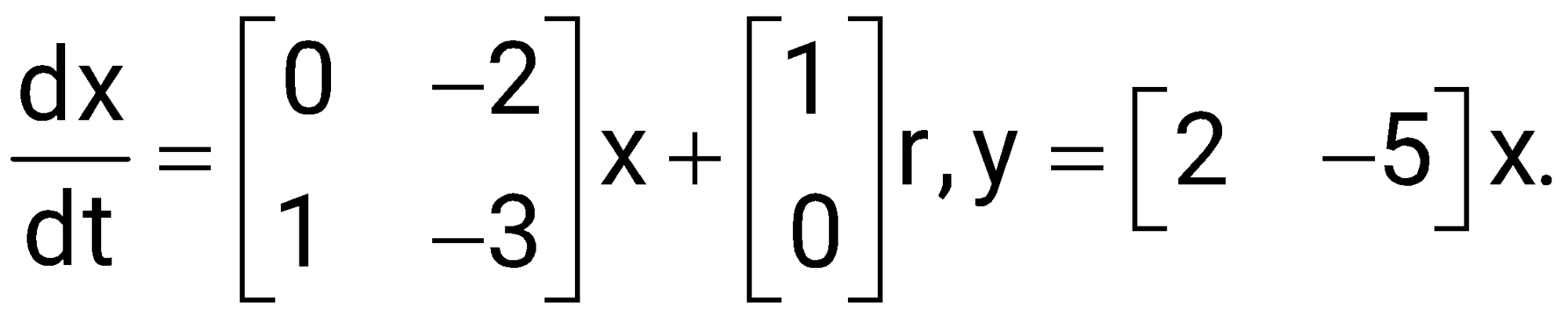
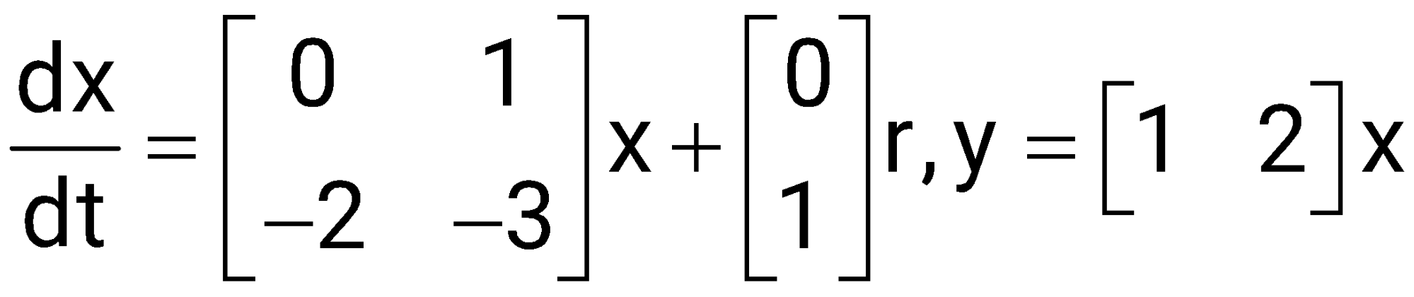
Which of the state space representations given below has/have the same transfer function as that of S?
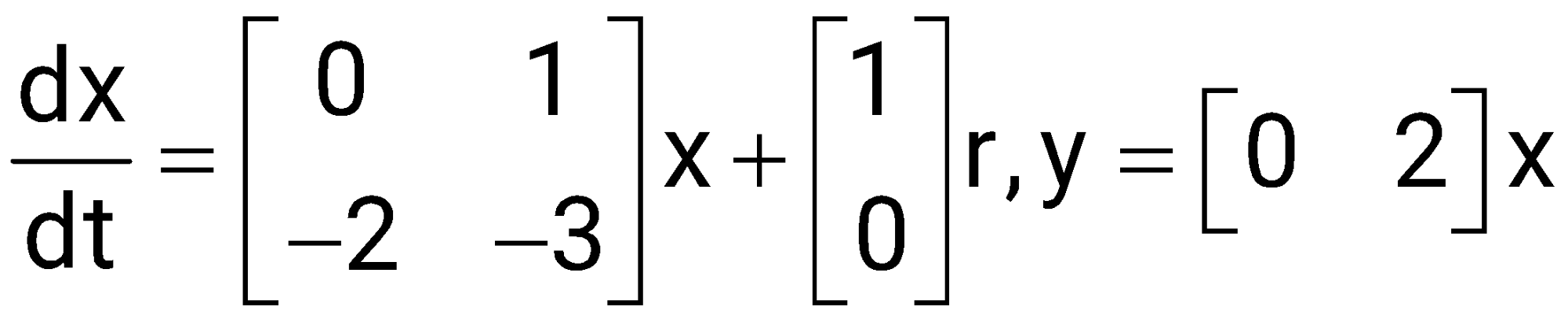
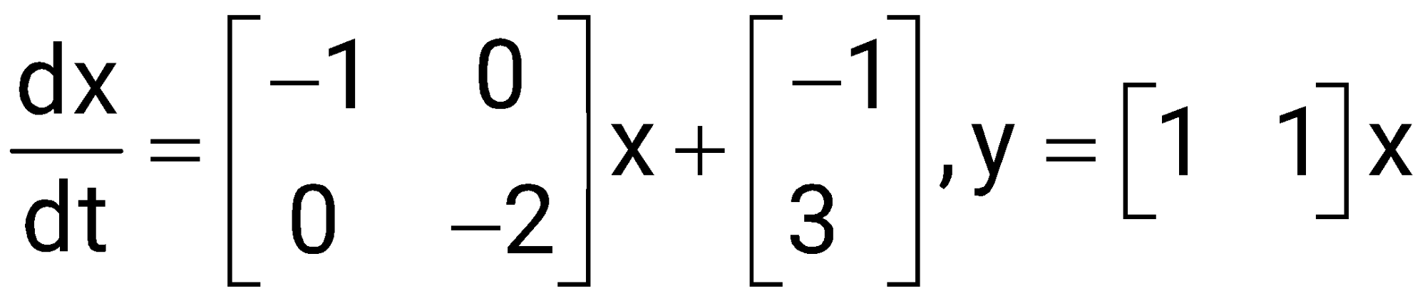
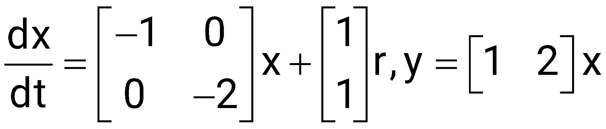
Sign in to see the solution
Log in to view the explanation, track your attempts, and keep your progress.
Sign in to UnlockThe state equation of a second order system is is the initial condition.
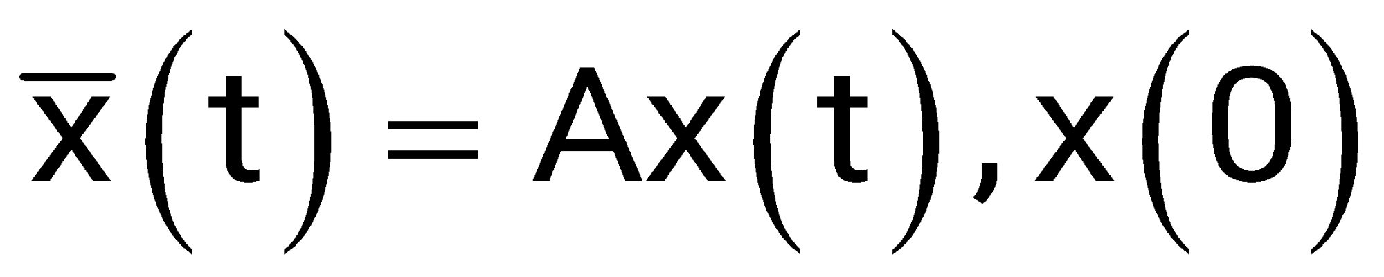
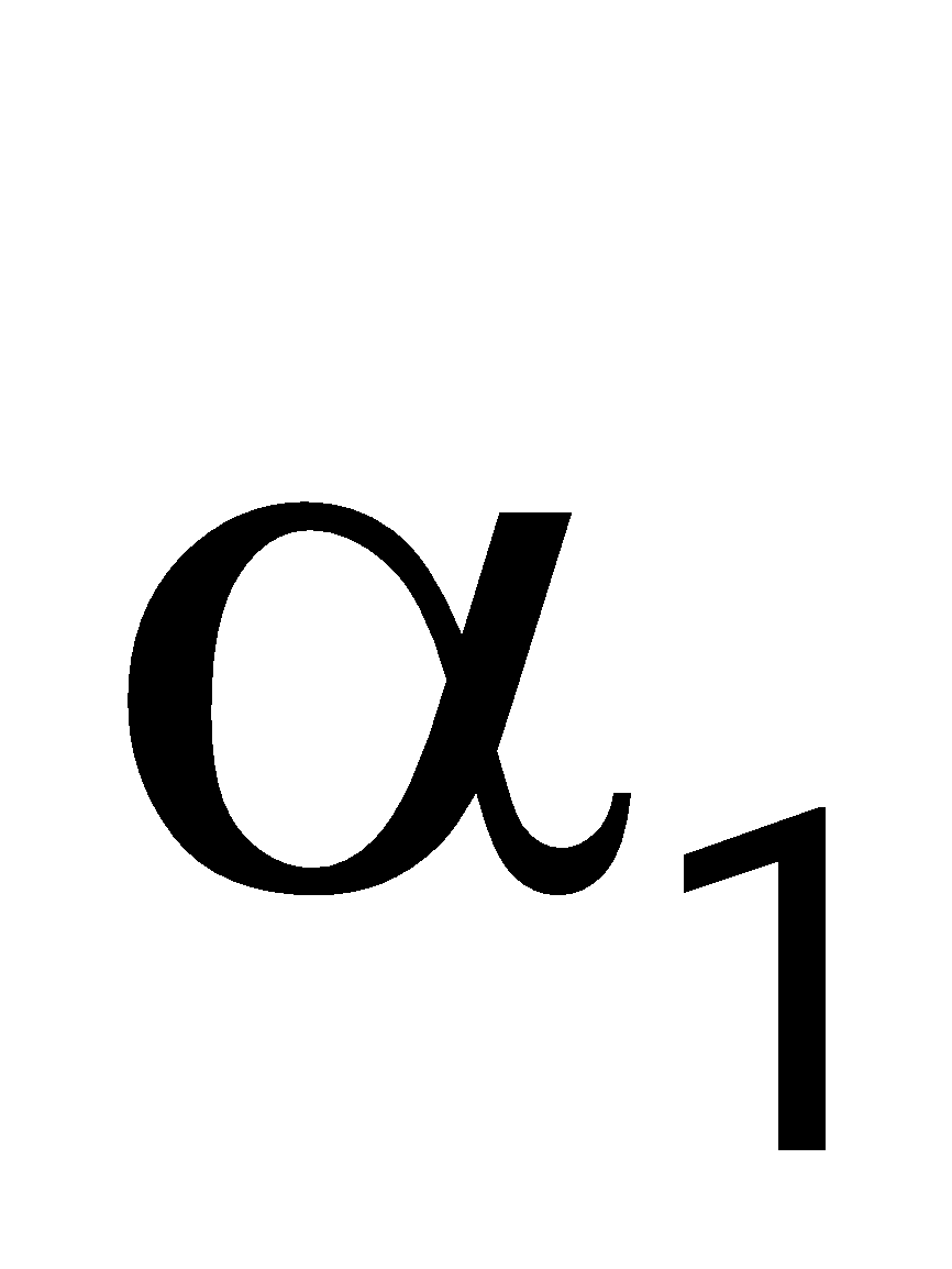
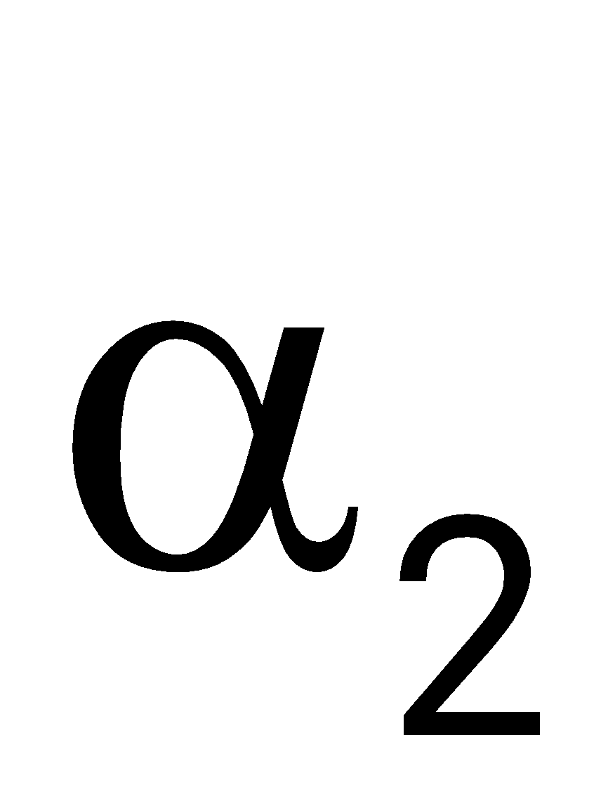
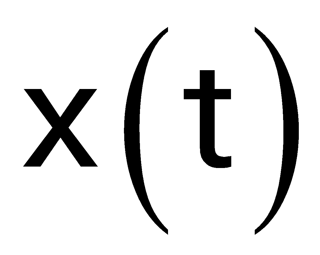
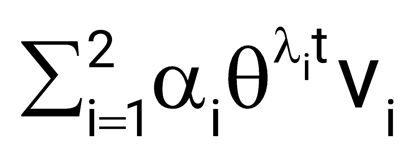
Suppose and are two distinct eigenvalues of A and and are the corresponding eigenvectors. For constants and , the solution, , of the state equation is
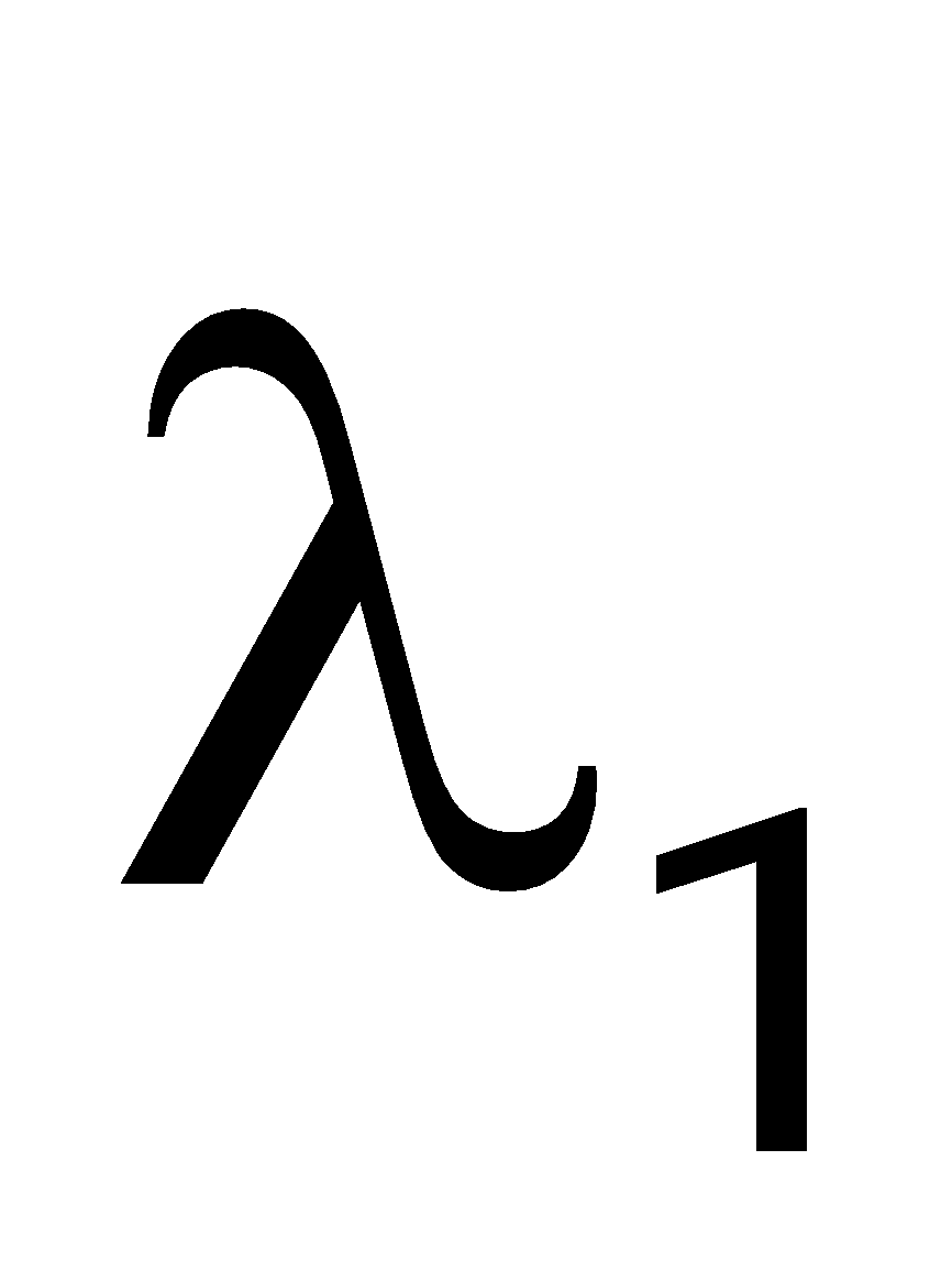
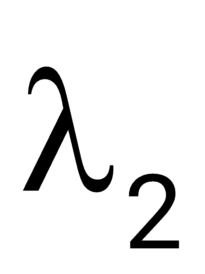
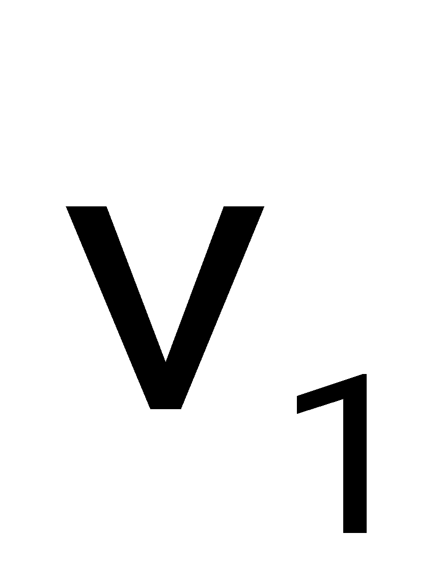
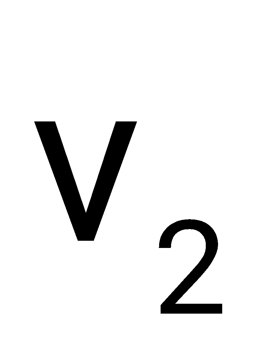
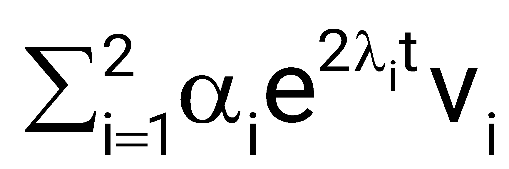
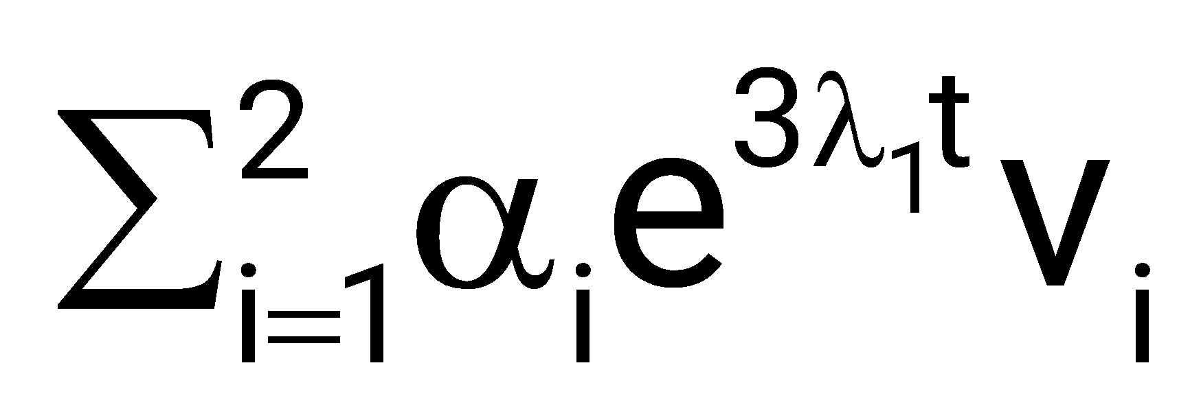
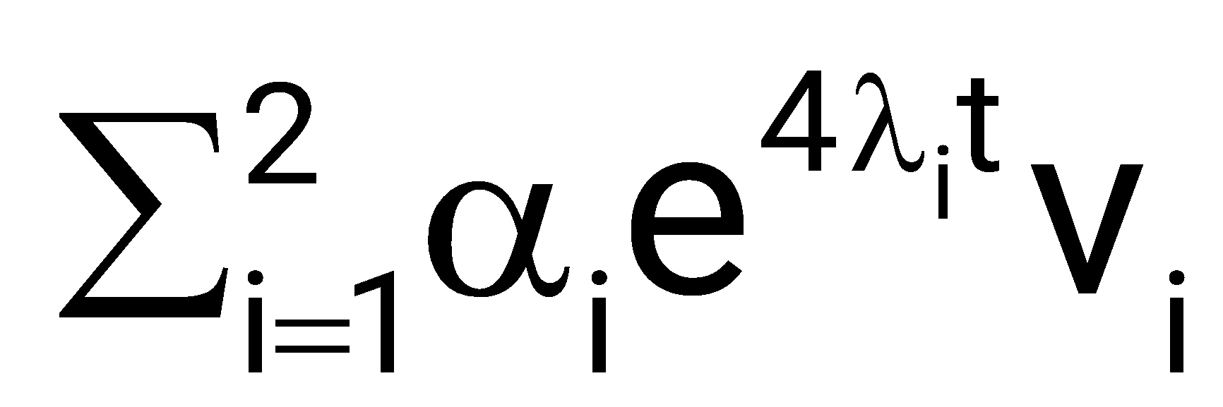
Sign in to see the solution
Log in to view the explanation, track your attempts, and keep your progress.
Sign in to UnlockThe electrical system shown in the figure converts input source current to output voltage .
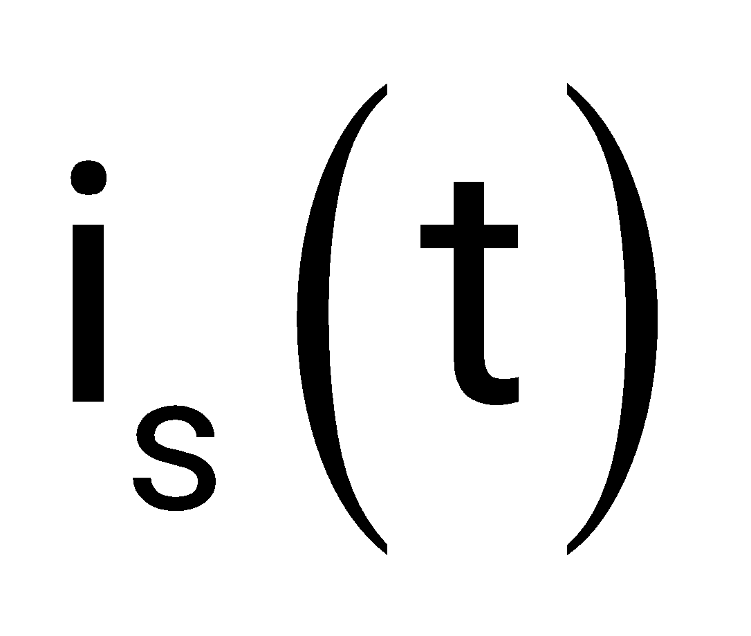
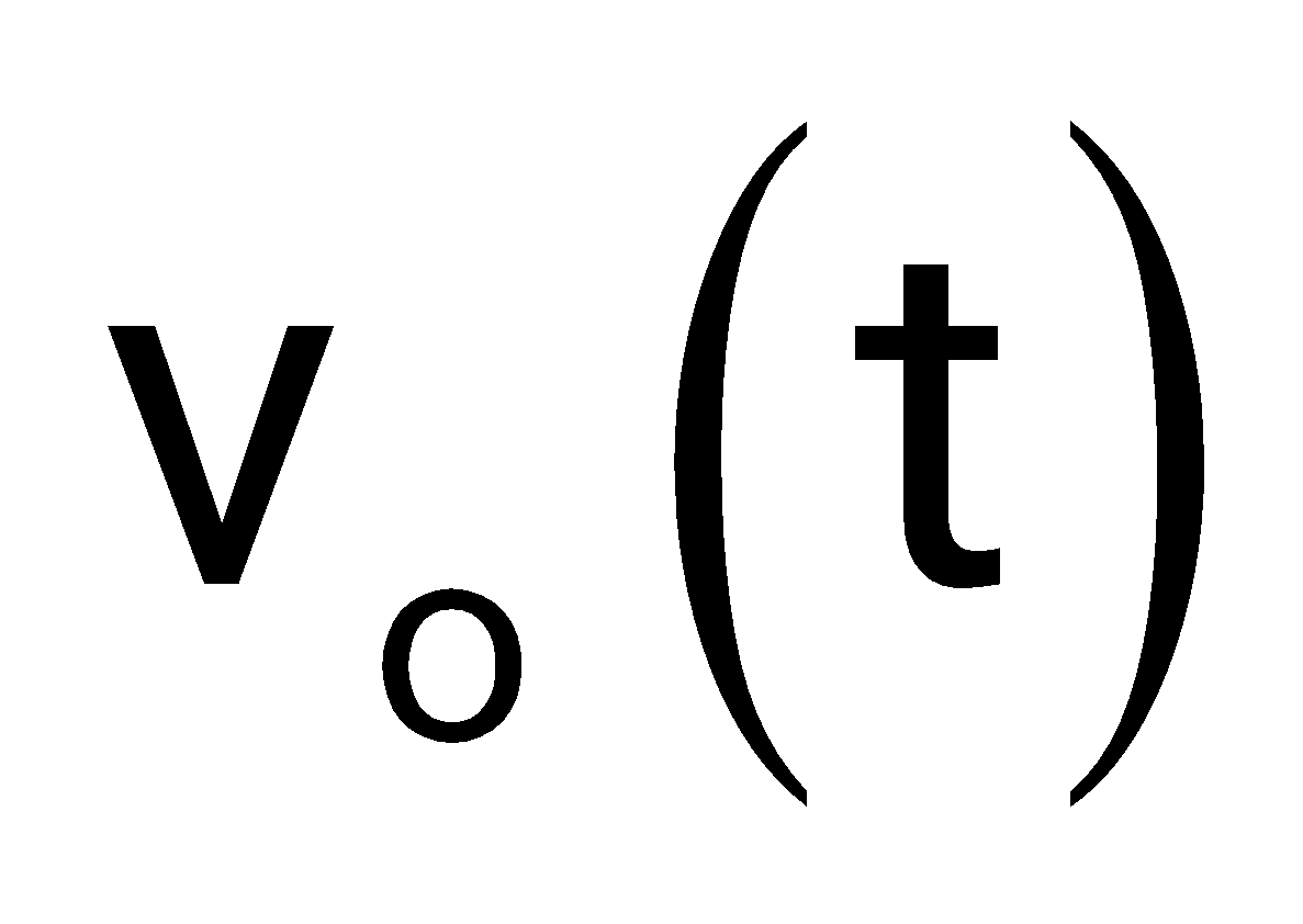
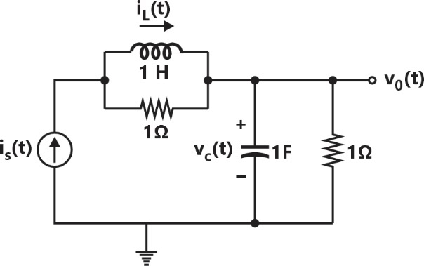
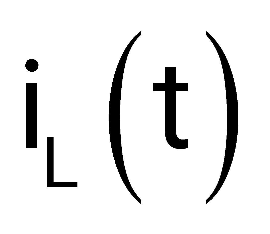
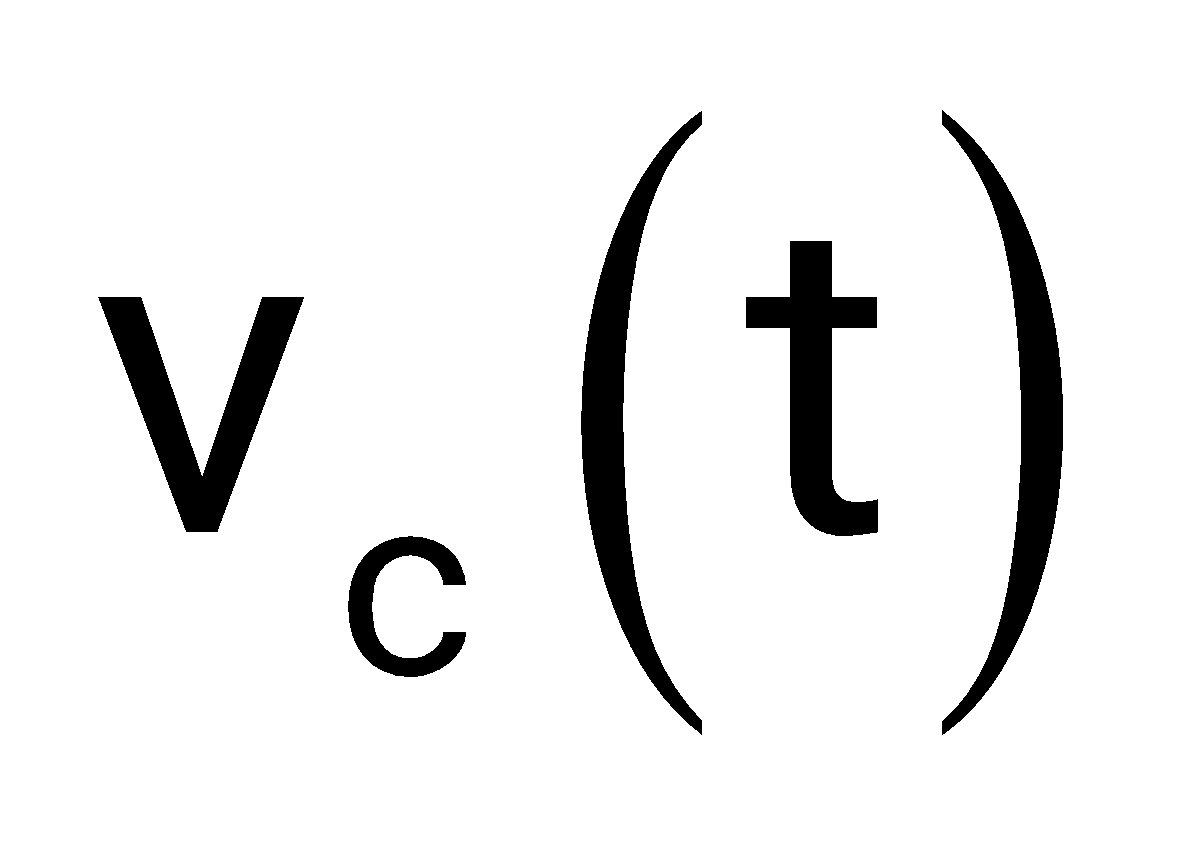
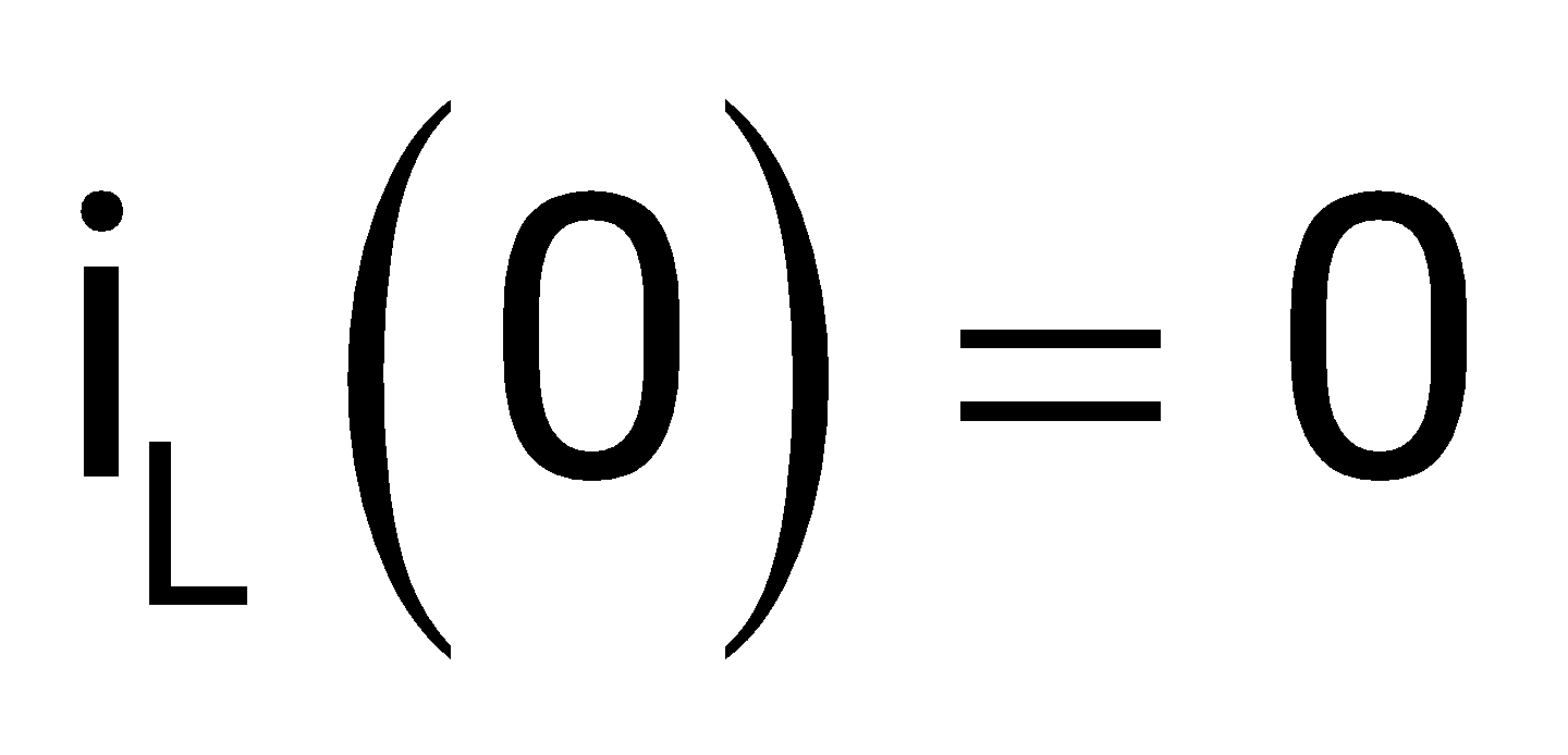
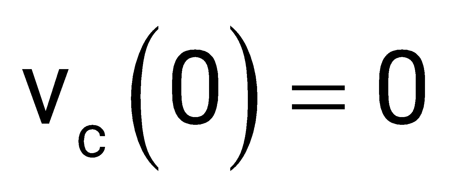
Current in the inductor and voltage across the capacitor are taken as the state variables, both assumed to be initially equal to zero, i.e., and . The system is
Sign in to see the solution
Log in to view the explanation, track your attempts, and keep your progress.
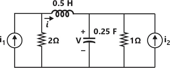
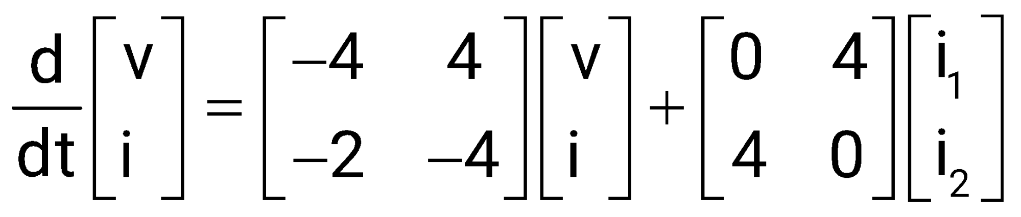
Sign in to UnlockFor the given circuit, which one of the following is the correct state equation?
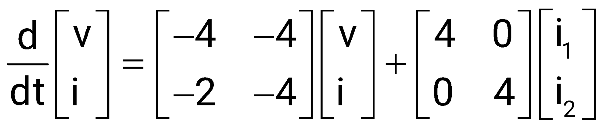
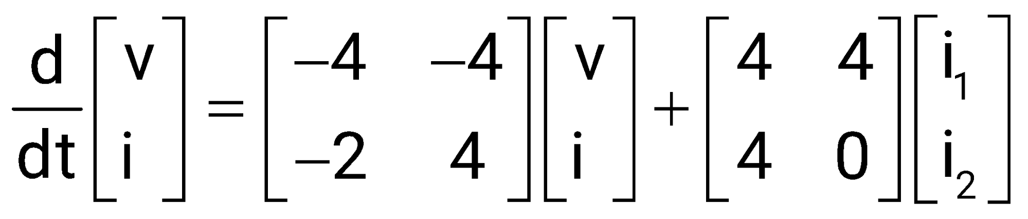
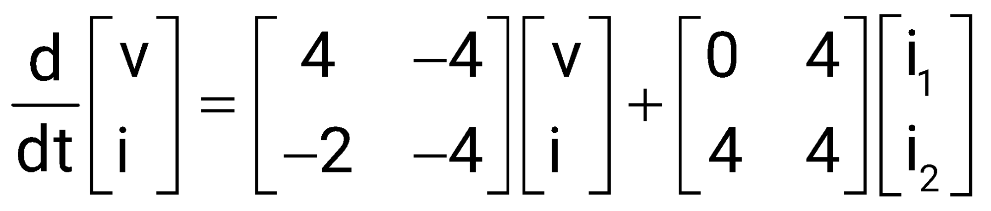
Sign in to see the solution
Log in to view the explanation, track your attempts, and keep your progress.
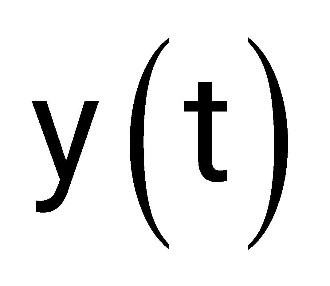
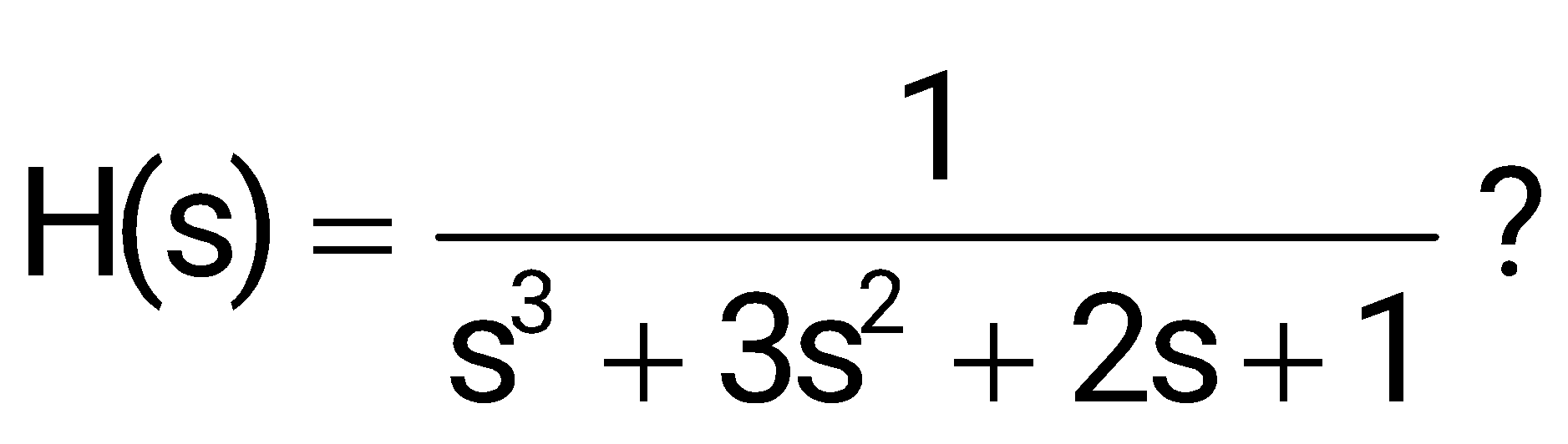
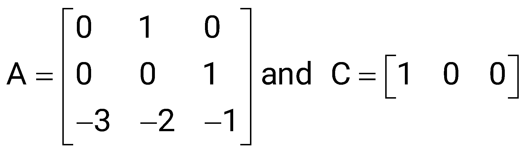
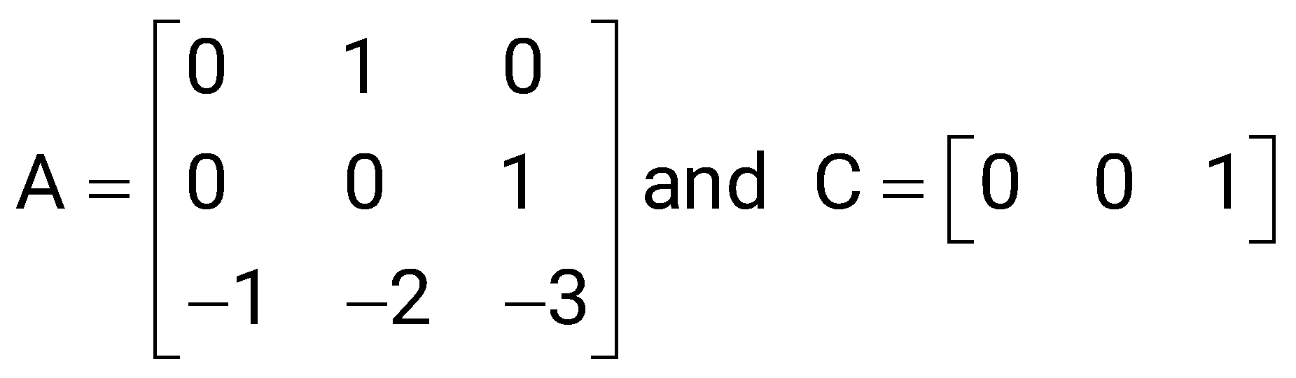
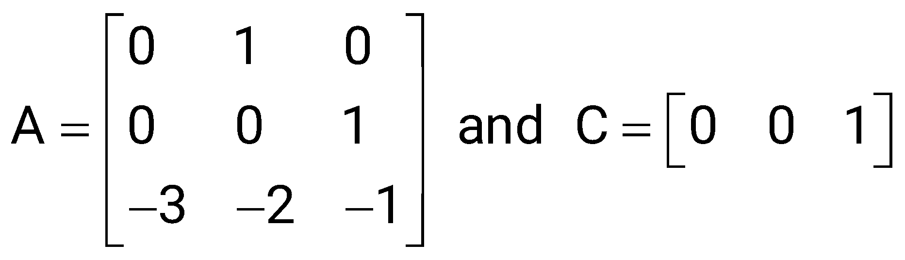
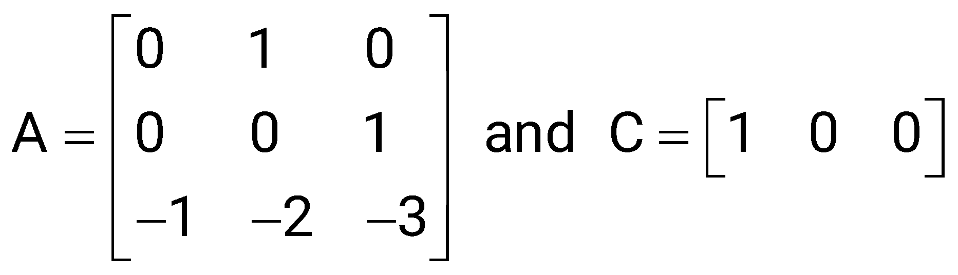
Sign in to UnlockLet the state-space representation of an LTI system be where A, B, C are matrices, d is a scalar, u(t) is the input to the system, and is its output. and
d = 0. Which one of the following options for A and C will ensure that the transfer function of this LTI system is


Sign in to see the solution
Log in to view the explanation, track your attempts, and keep your progress.
Sign in to UnlockThe state equation and the output equation of a control system are given below:
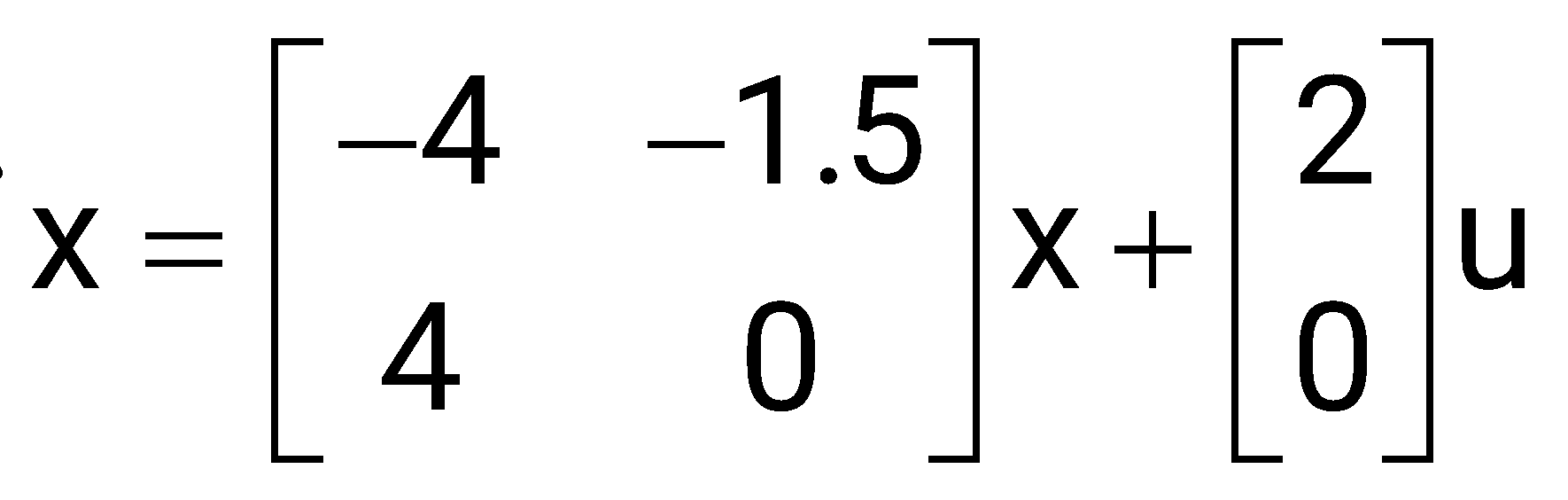
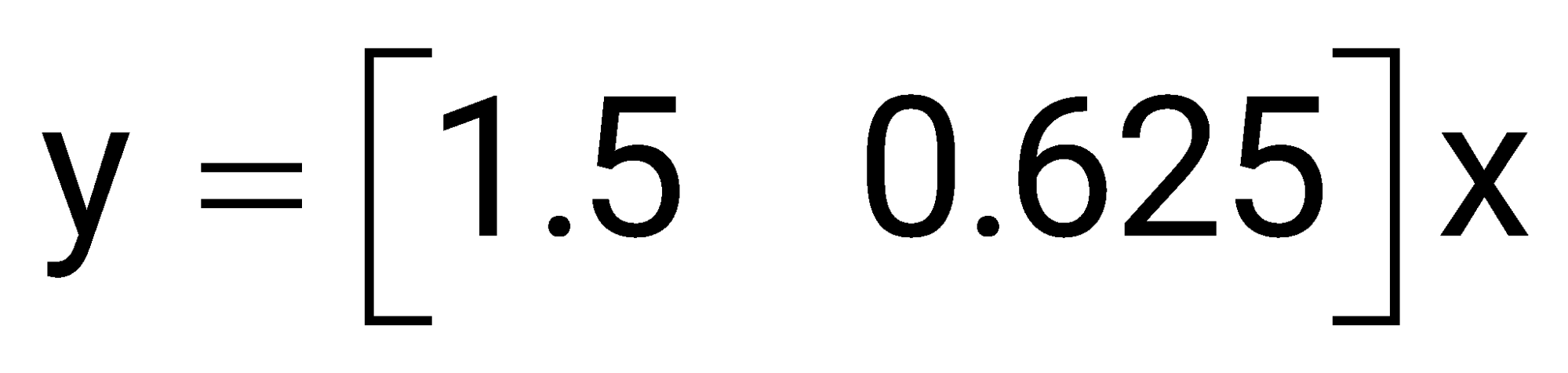
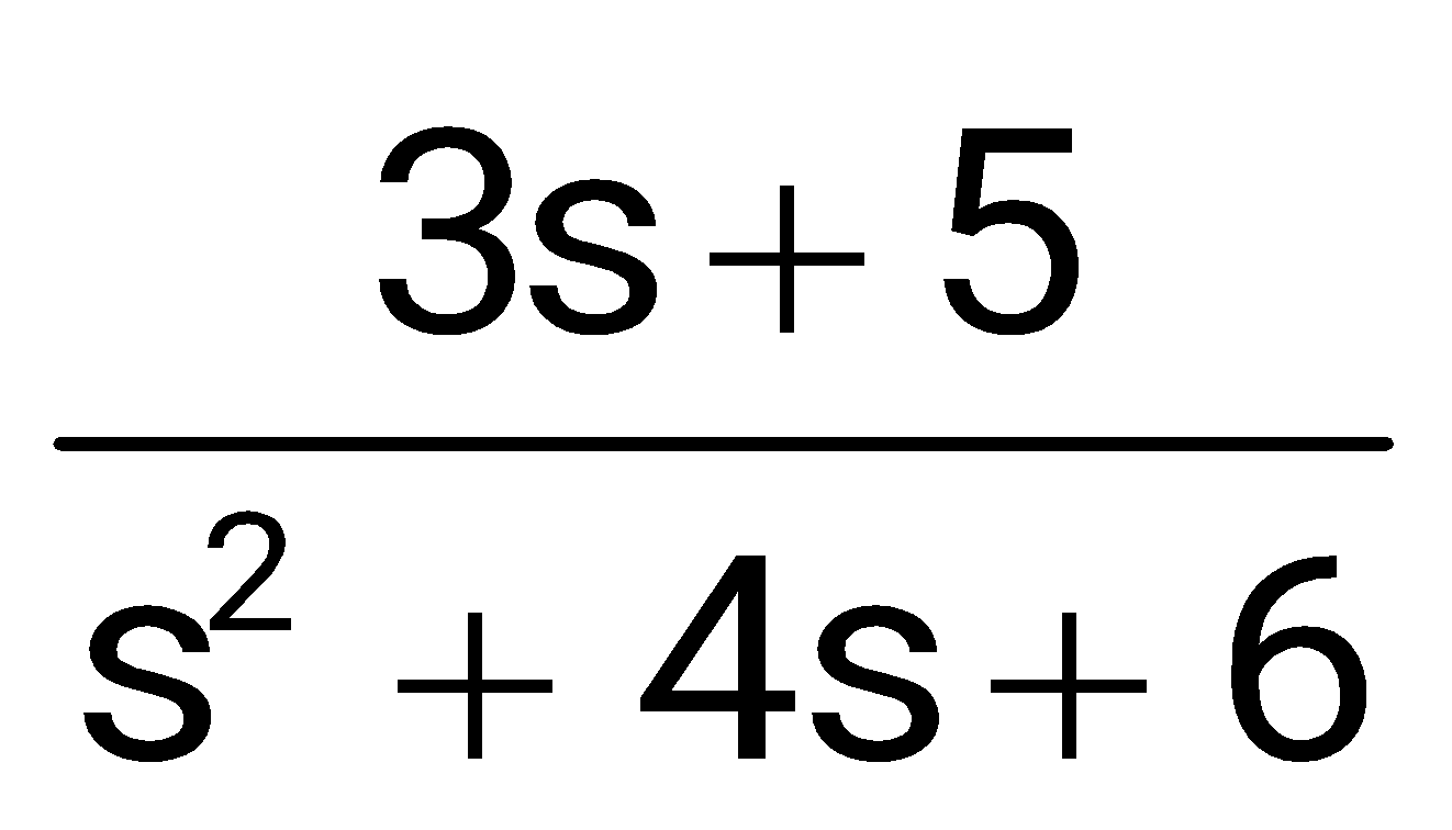
The transfer function representation of the system is
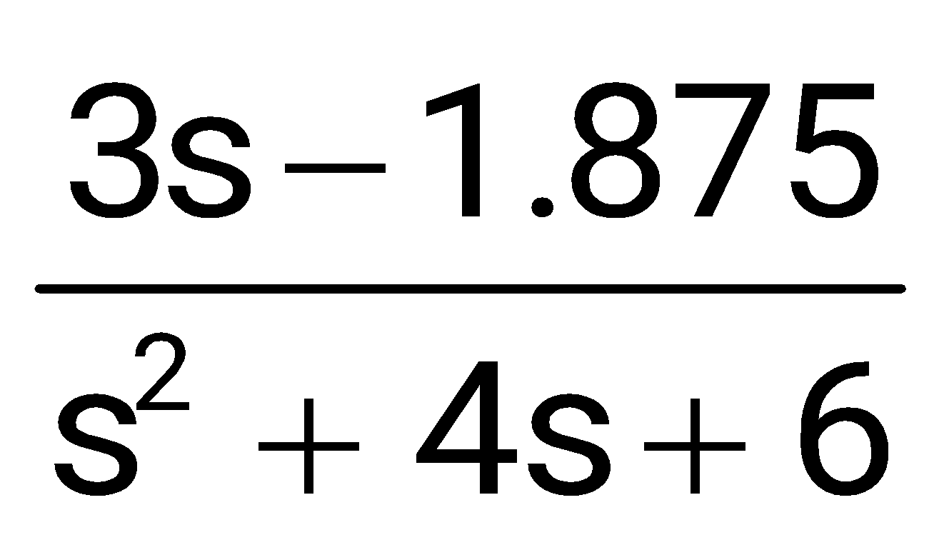
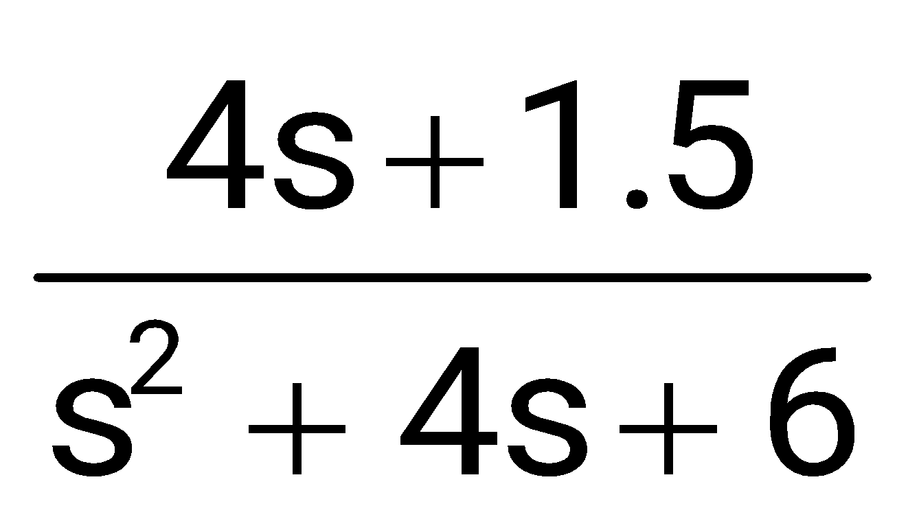
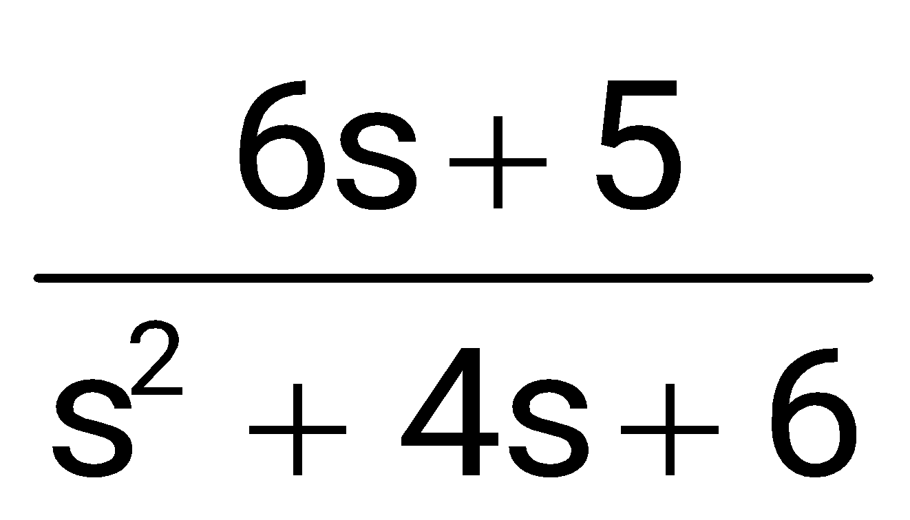
Sign in to see the solution
Log in to view the explanation, track your attempts, and keep your progress.
Sign in to UnlockConsider the state space realization
, with the initial condition,
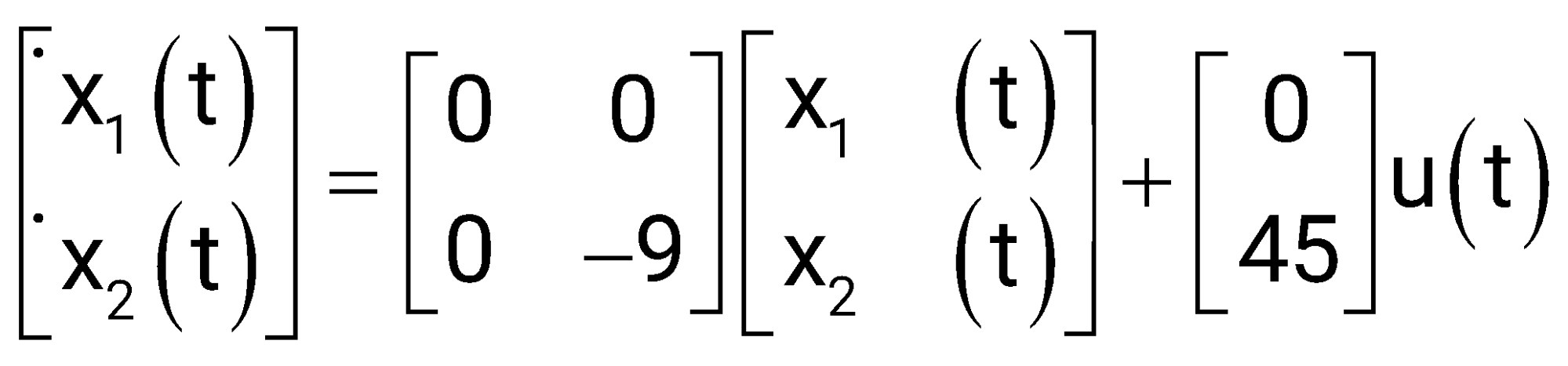
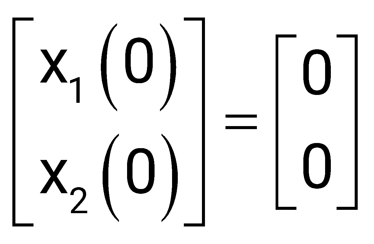
Where u (t) denotes the unit step function. The value of

Sign in to see the solution
Log in to view the explanation, track your attempts, and keep your progress.
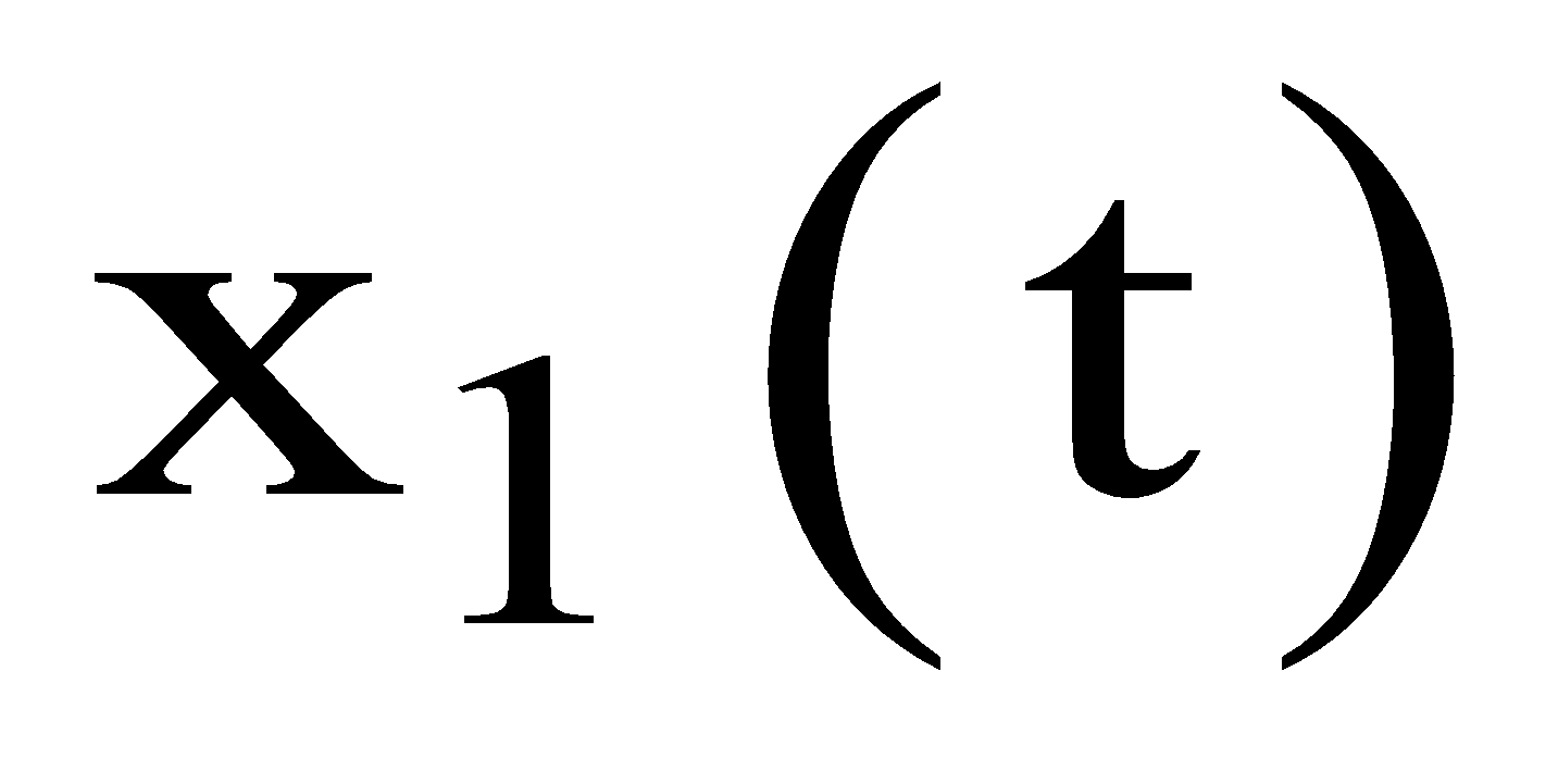
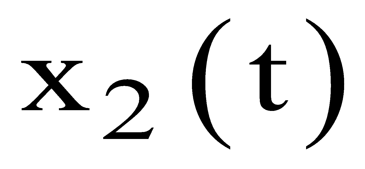
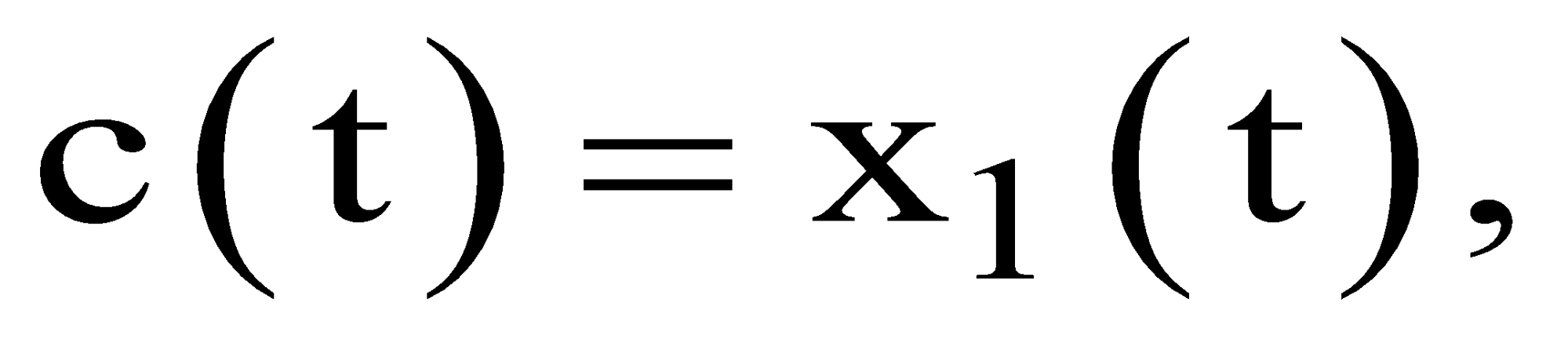
Sign in to UnlockA second-order linear time-invariant system is described by the following state equations
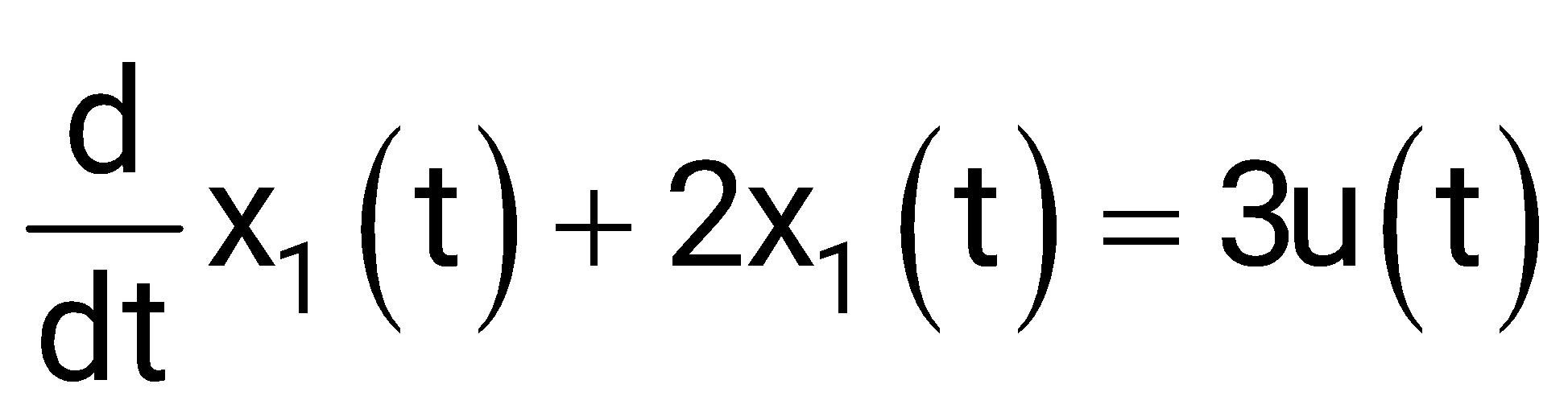
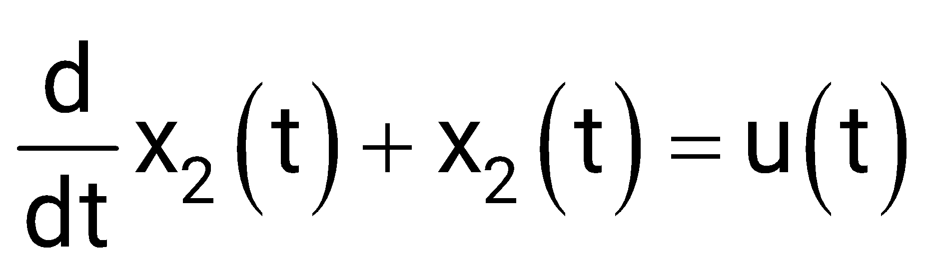
Where and are the two state variables and u(t) denotes the input. If the output then the system is
Sign in to see the solution
Log in to view the explanation, track your attempts, and keep your progress.
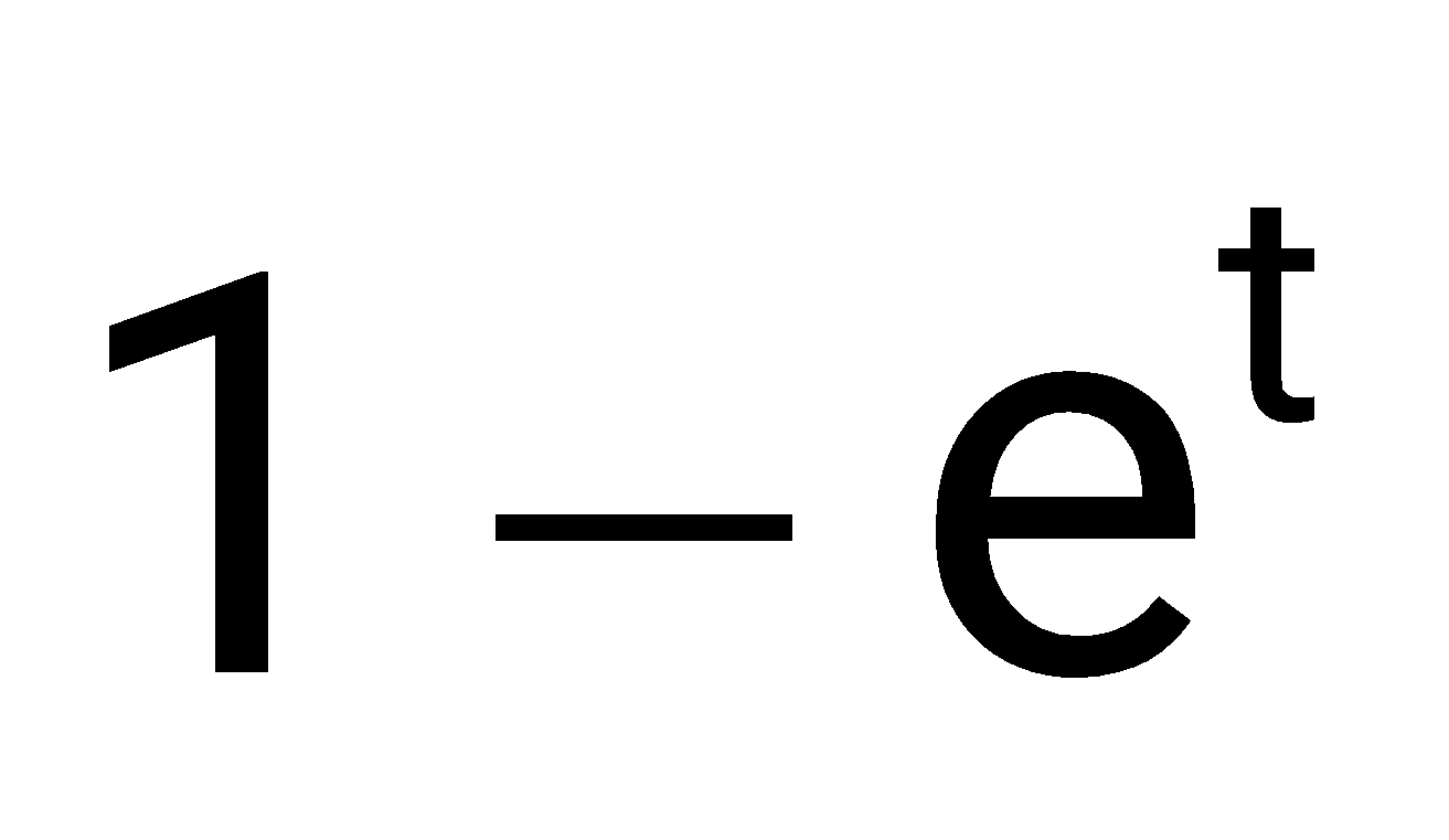
Sign in to UnlockThe state variable representation of a system is given as and .
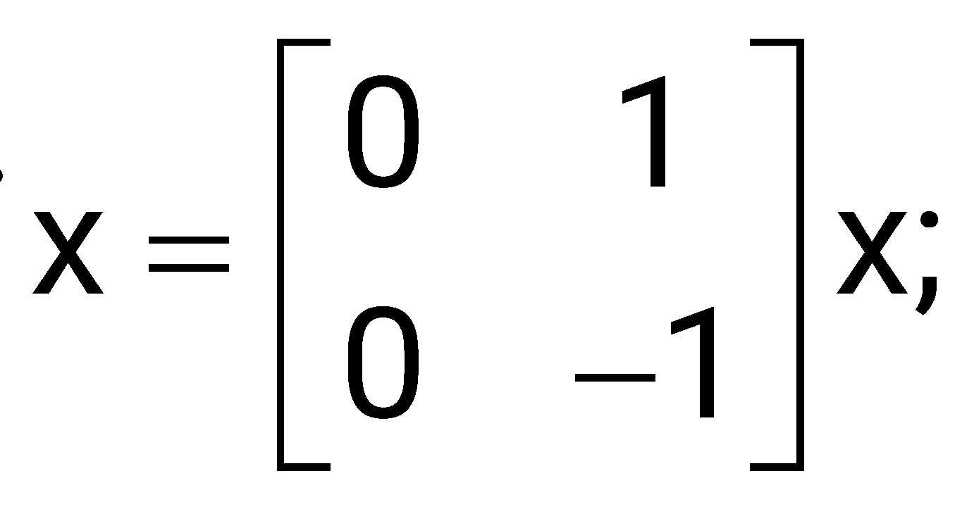
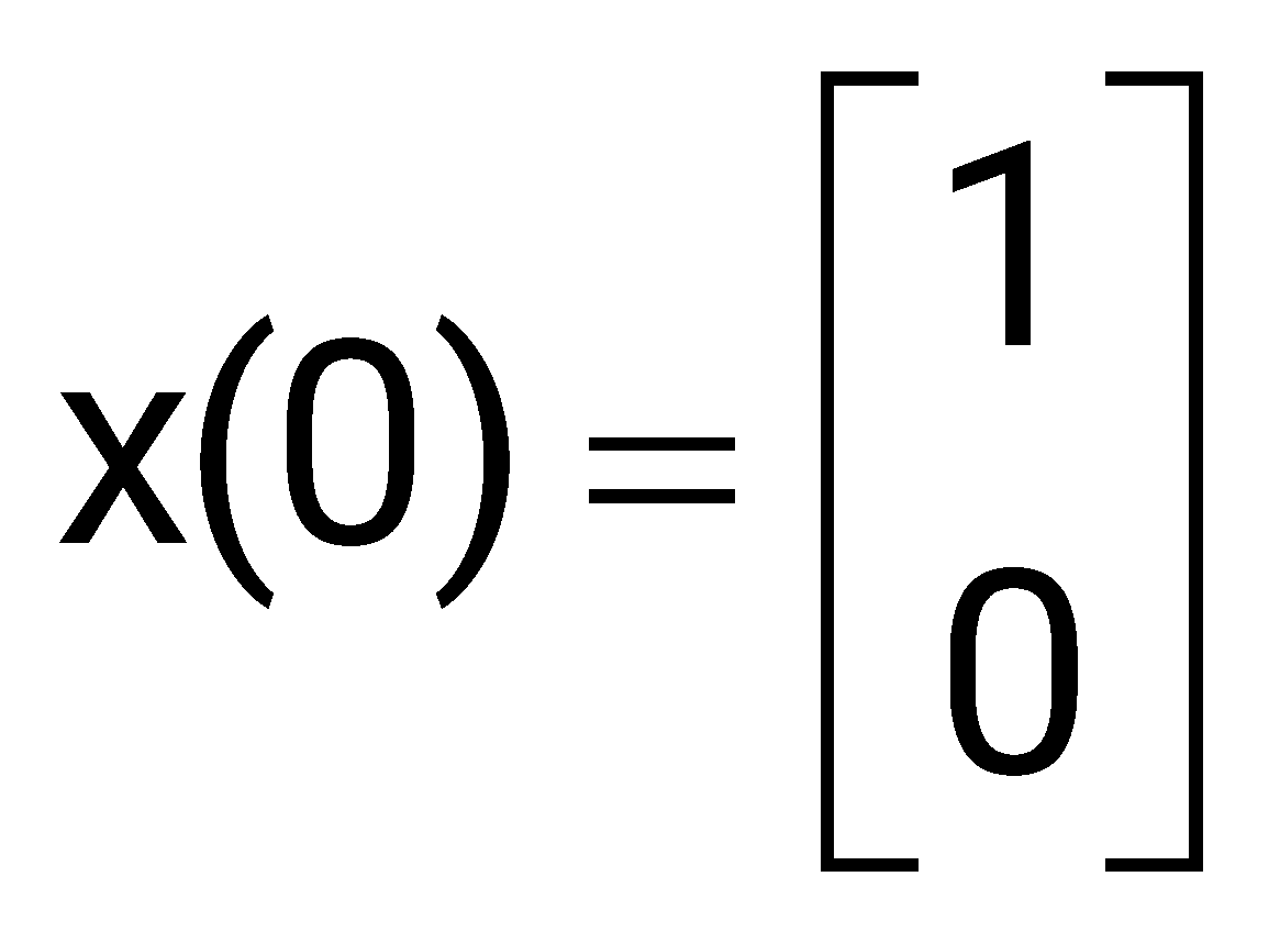
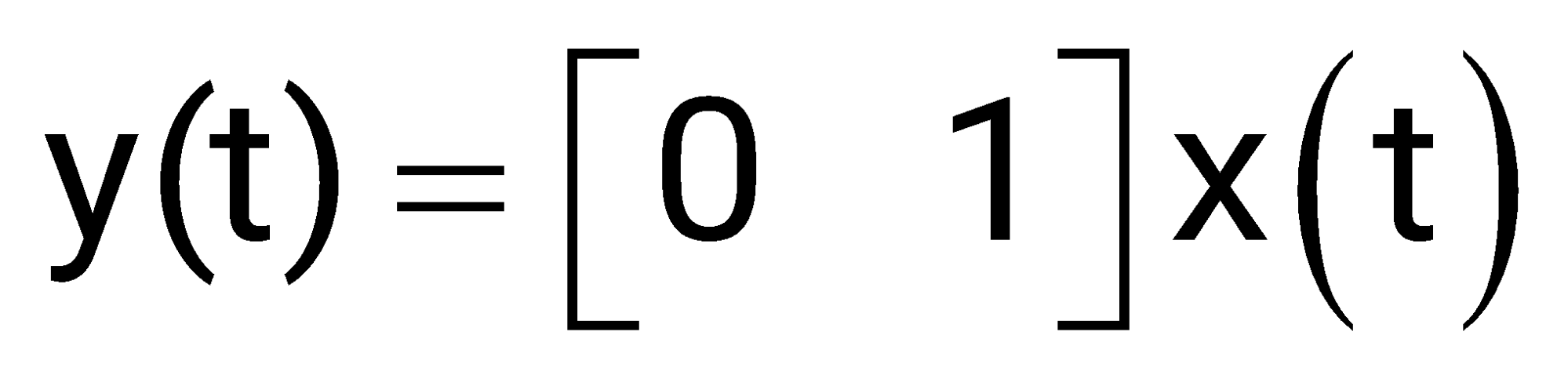
The response y(t) is
sin (t)
1-cos(t)
0
Sign in to see the solution
Log in to view the explanation, track your attempts, and keep your progress.
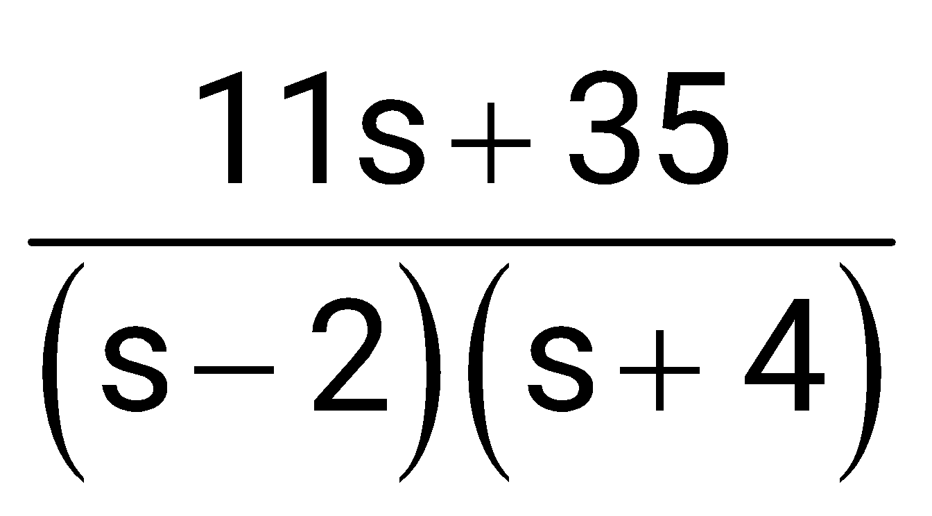
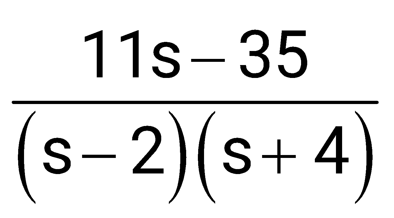
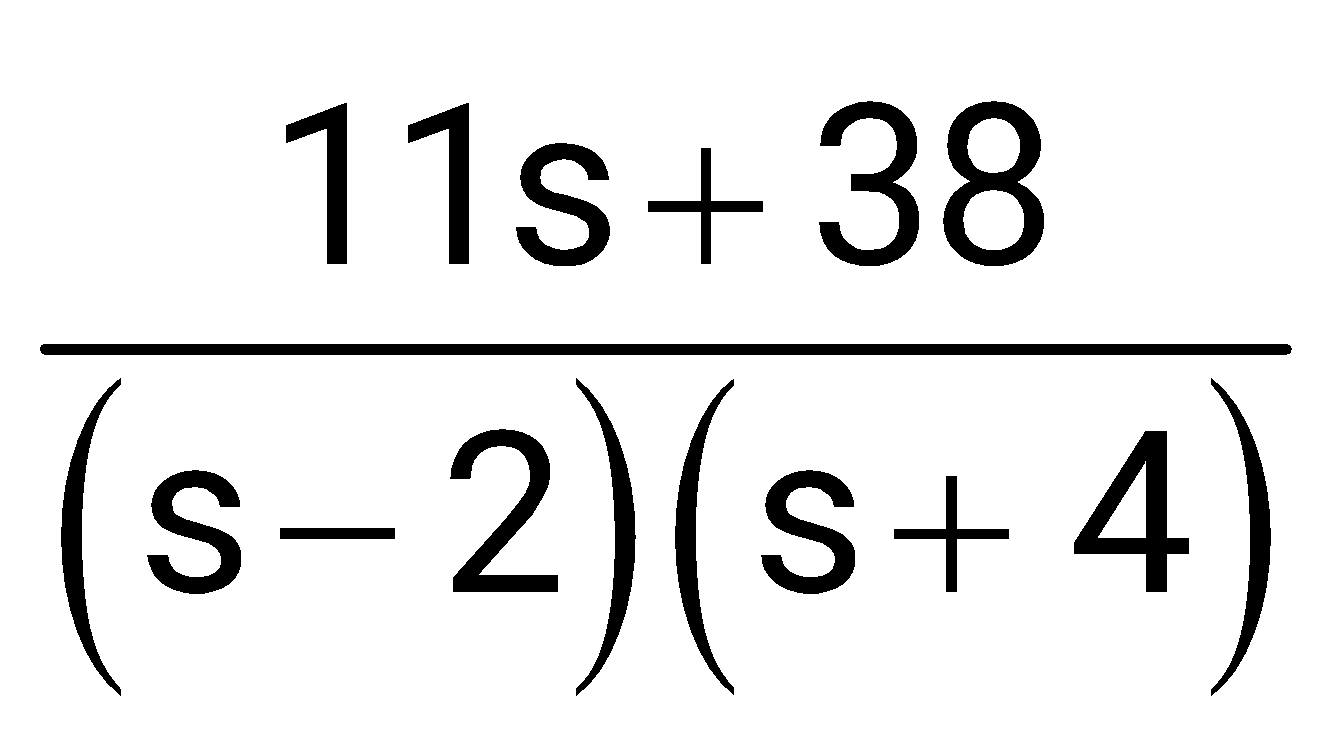
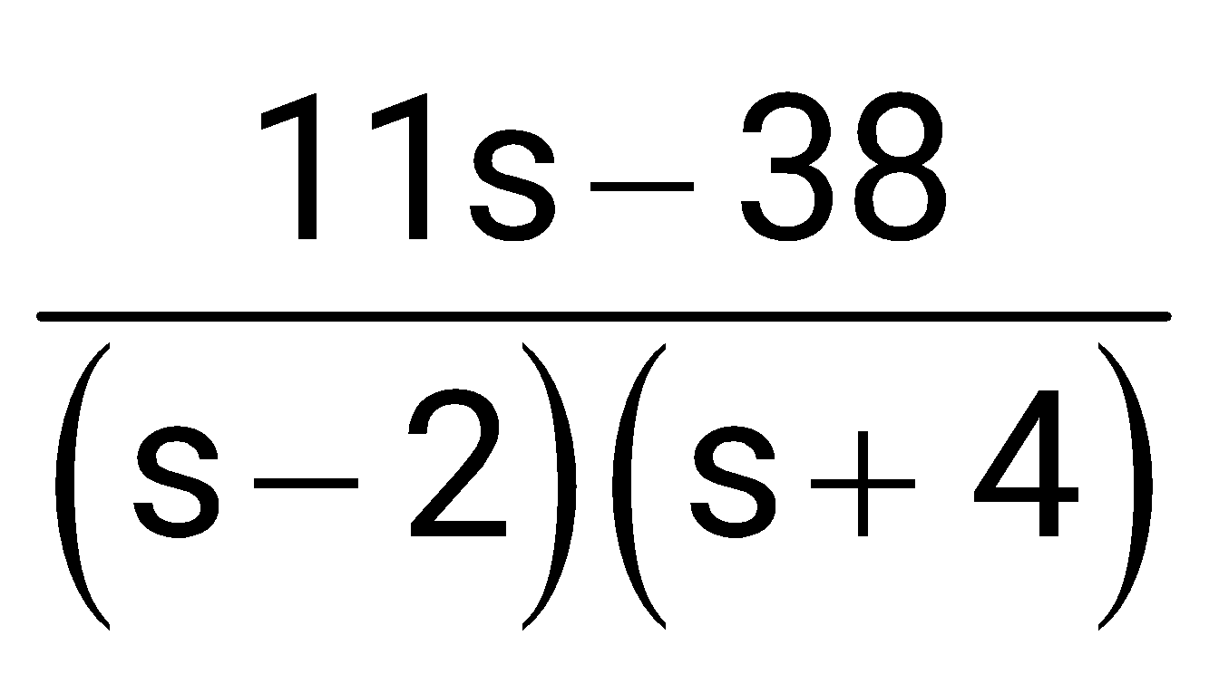
Sign in to UnlockA network is described by the state model as
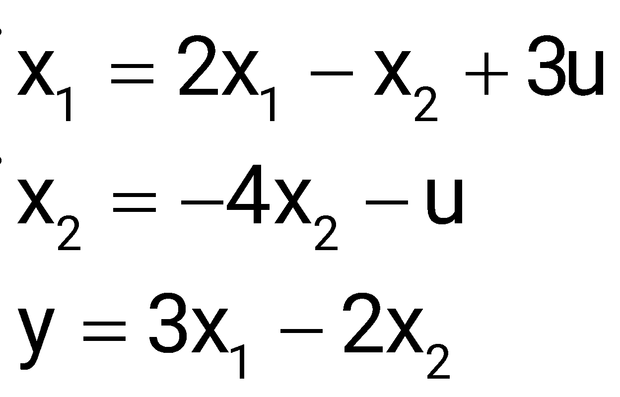
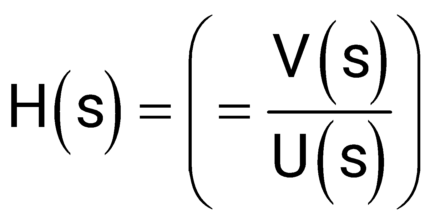
The transfer function
is
Sign in to see the solution
Log in to view the explanation, track your attempts, and keep your progress.
Sign in to UnlockConsider the state space model of a system, as
given below ;
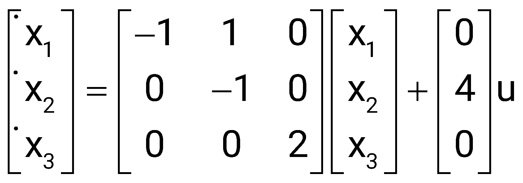
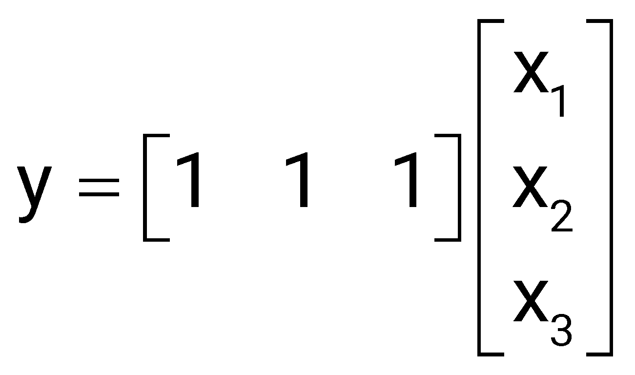
The system is
Sign in to see the solution
Log in to view the explanation, track your attempts, and keep your progress.
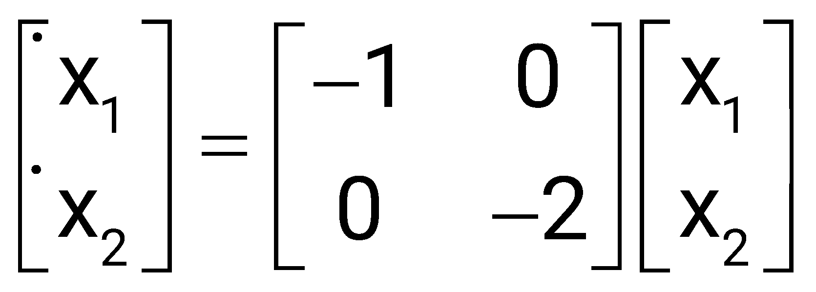
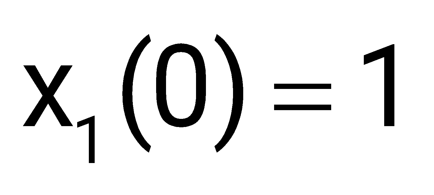
Sign in to UnlockAn unforced linear time invariant (LTI) system is represented by . If the initial conditions are and, the solution of the state equation is
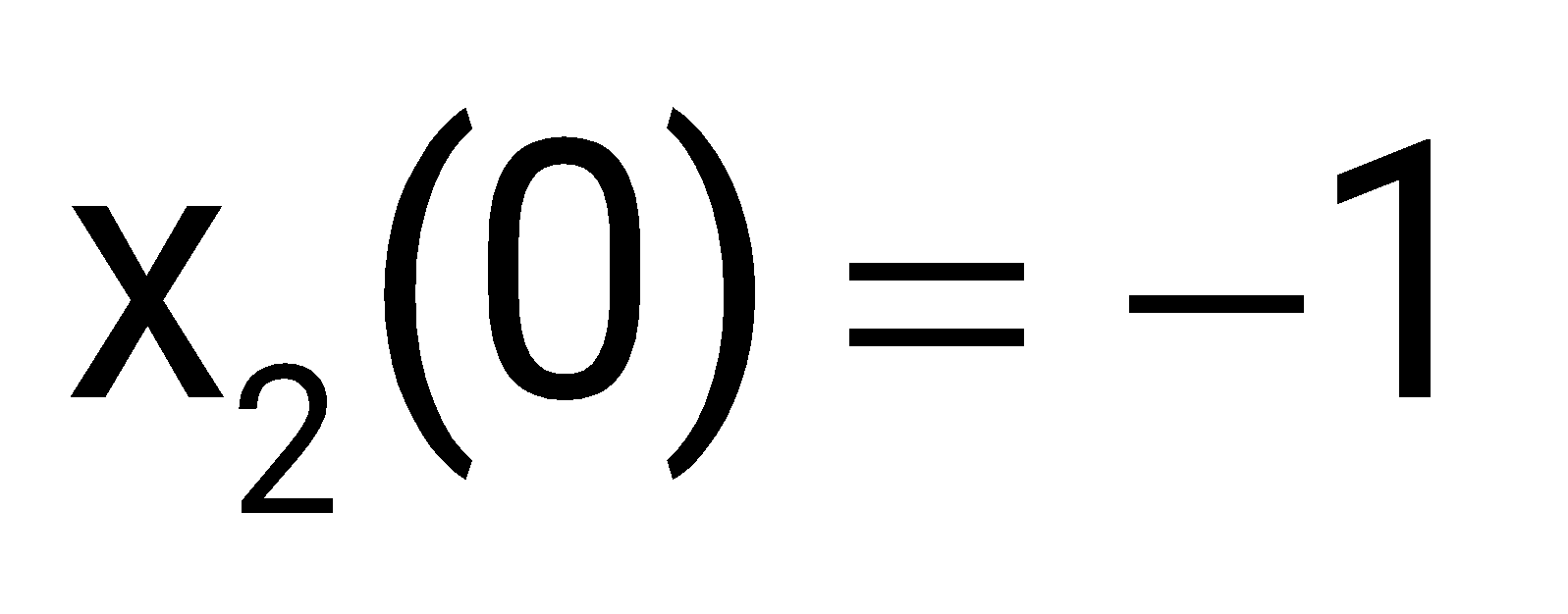
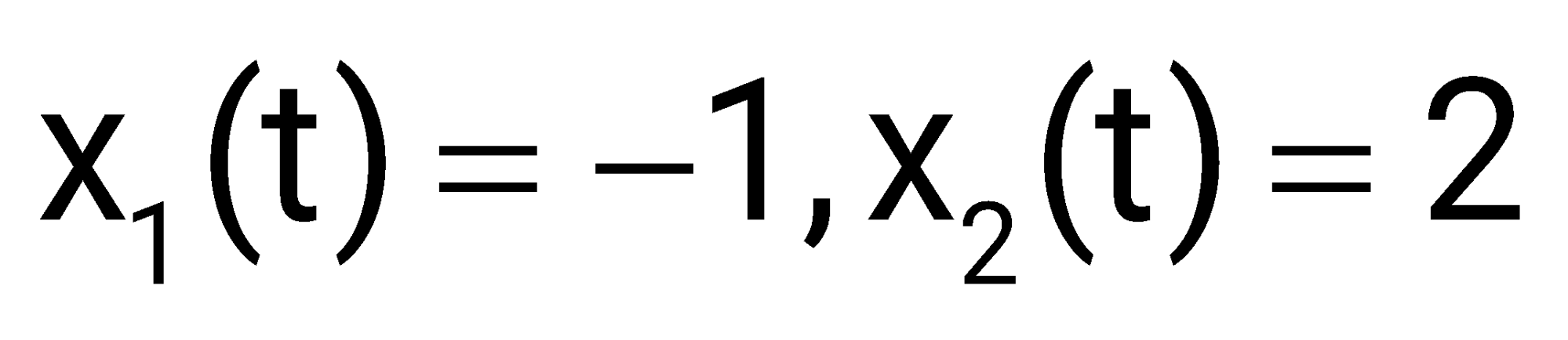



Sign in to see the solution
Log in to view the explanation, track your attempts, and keep your progress.
Sign in to UnlockConsider the state space system expressed by the signal flow diagram shown in the figure.
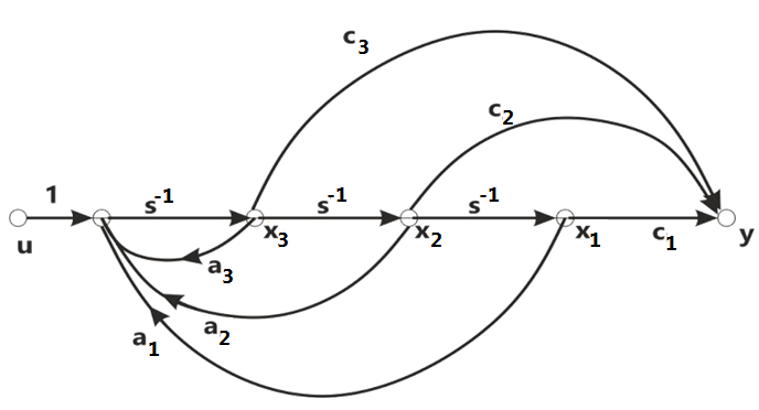
The corresponding system is
Sign in to see the solution
Log in to view the explanation, track your attempts, and keep your progress.
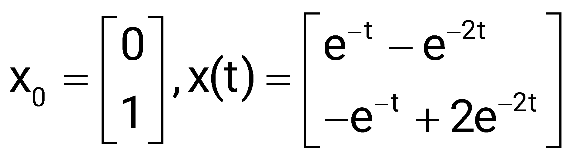
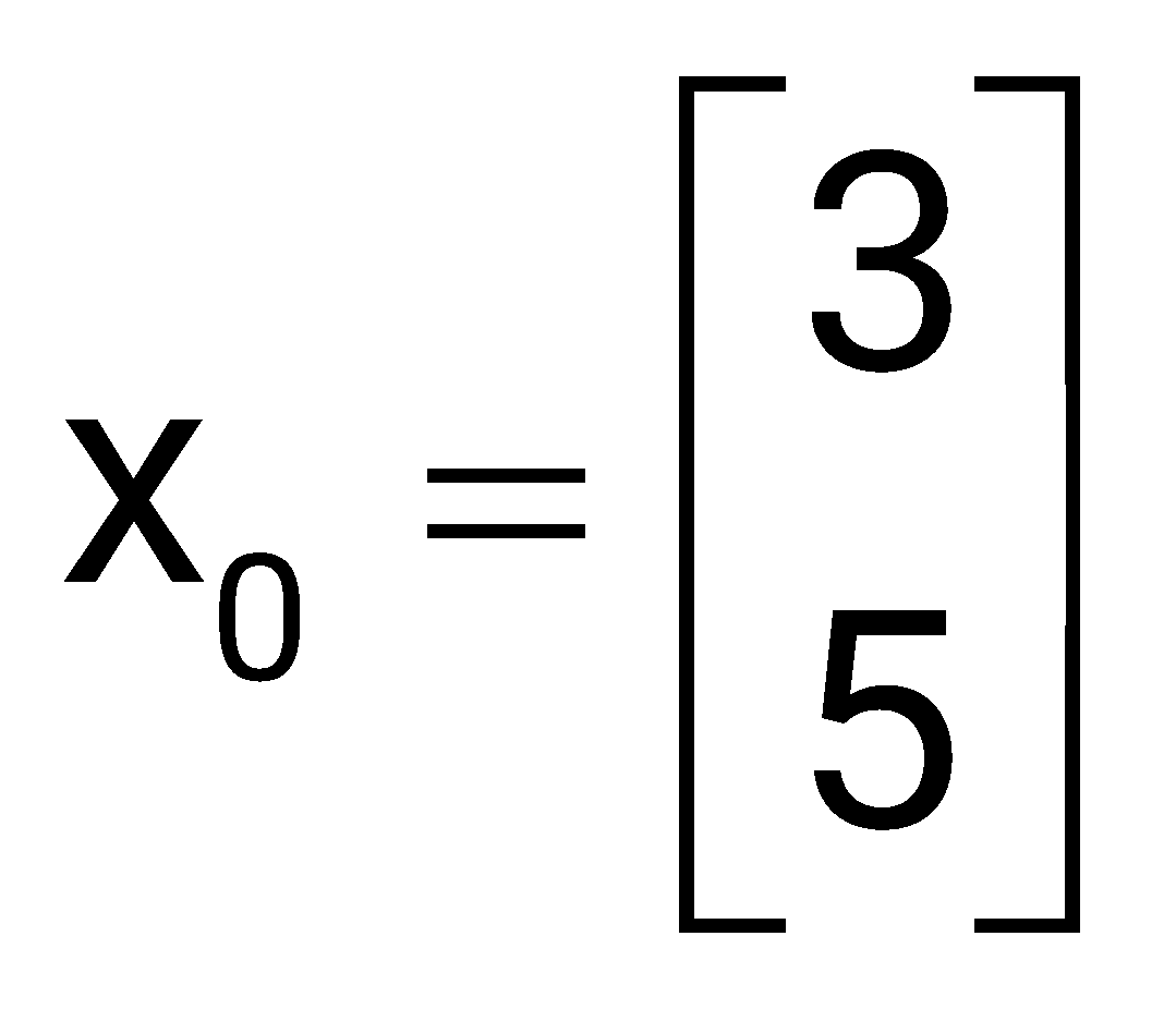
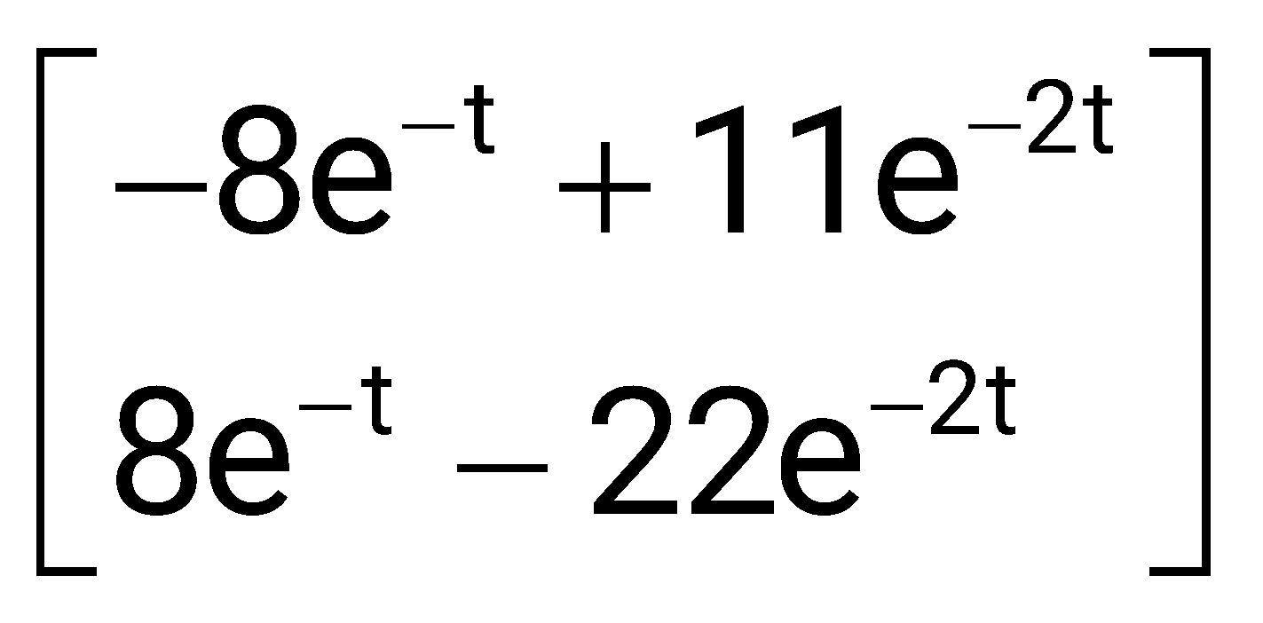
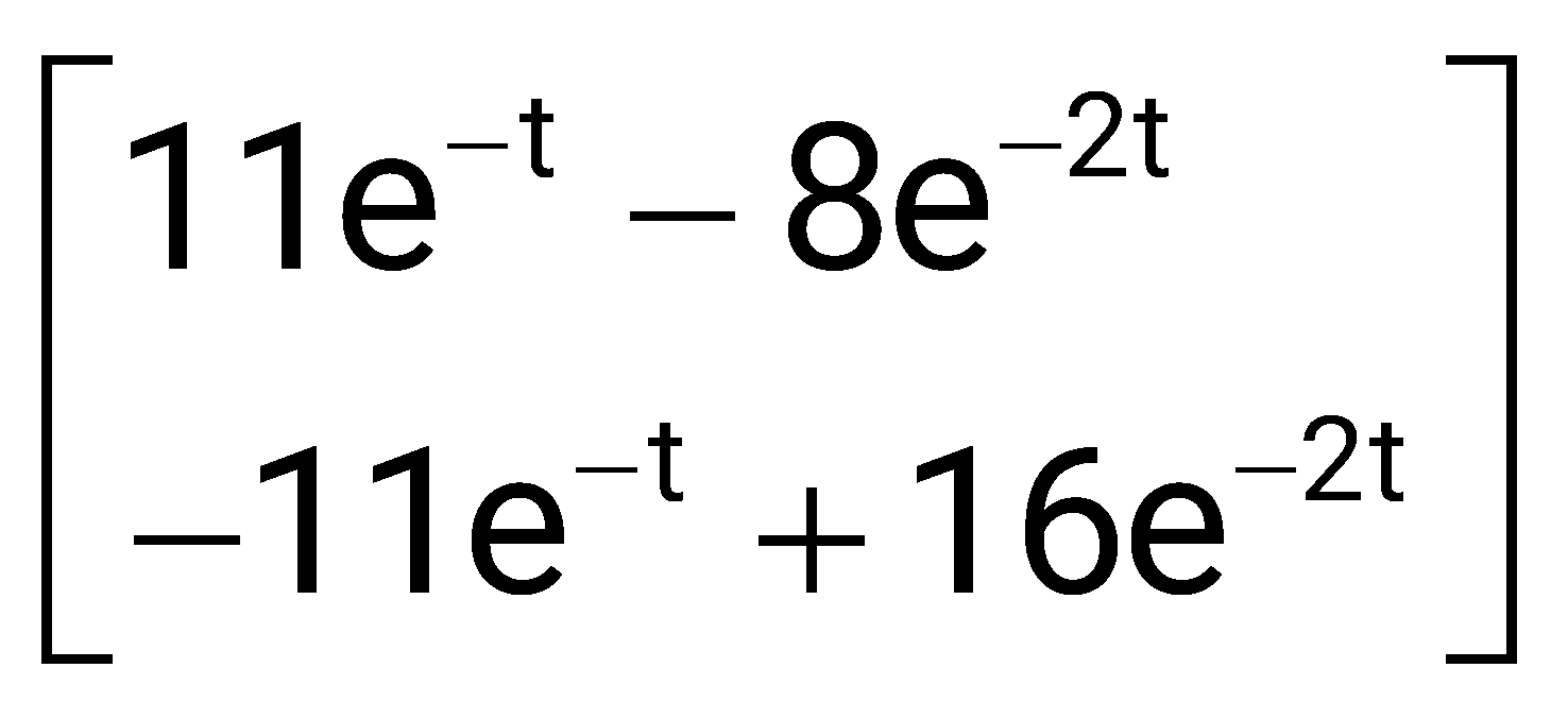
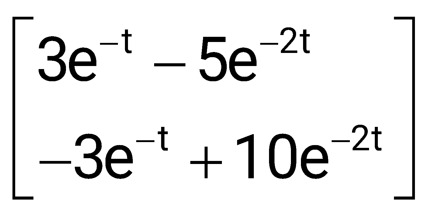
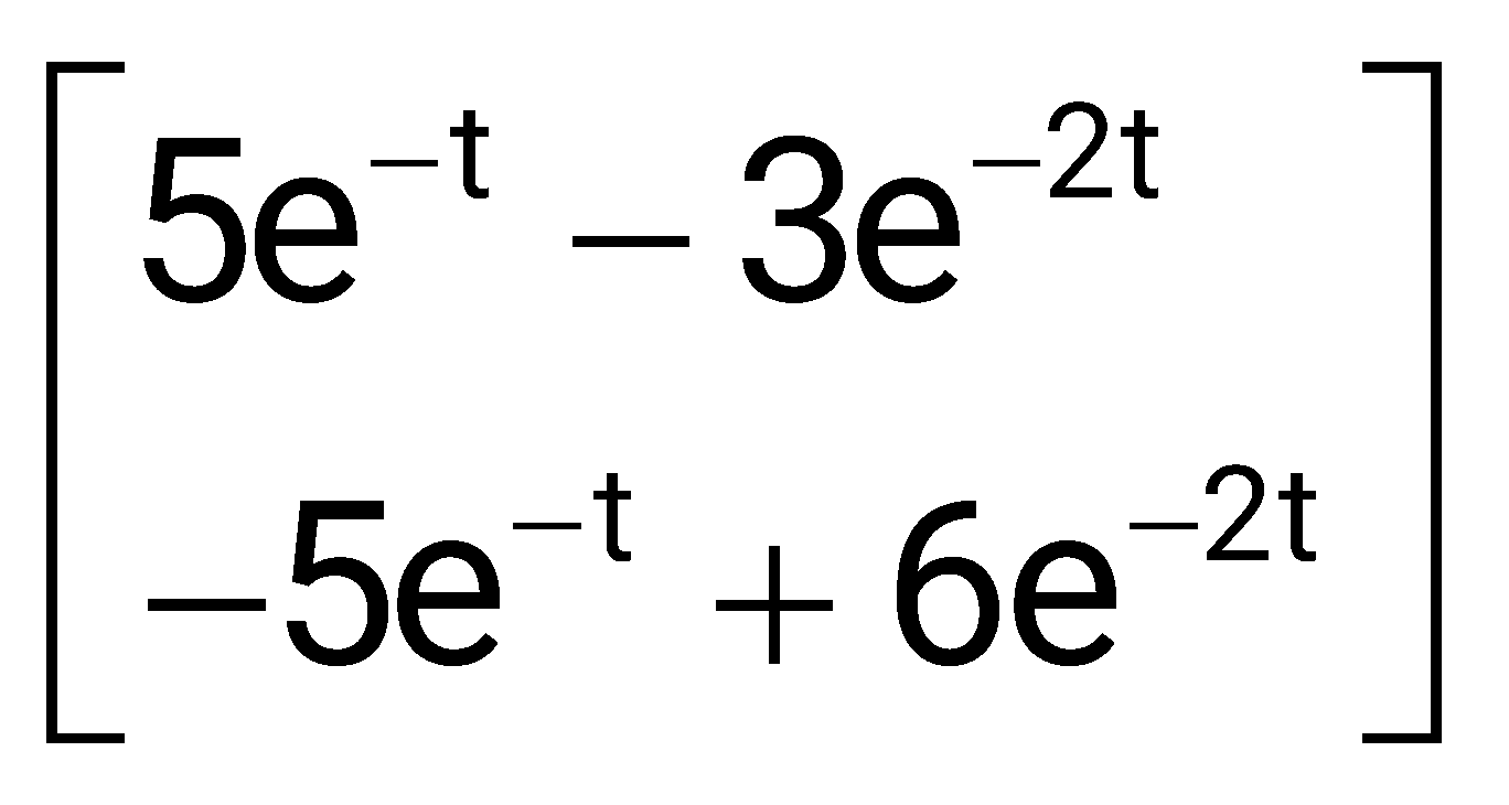
Sign in to UnlockThe state equation of a second-order linear system is given by
and
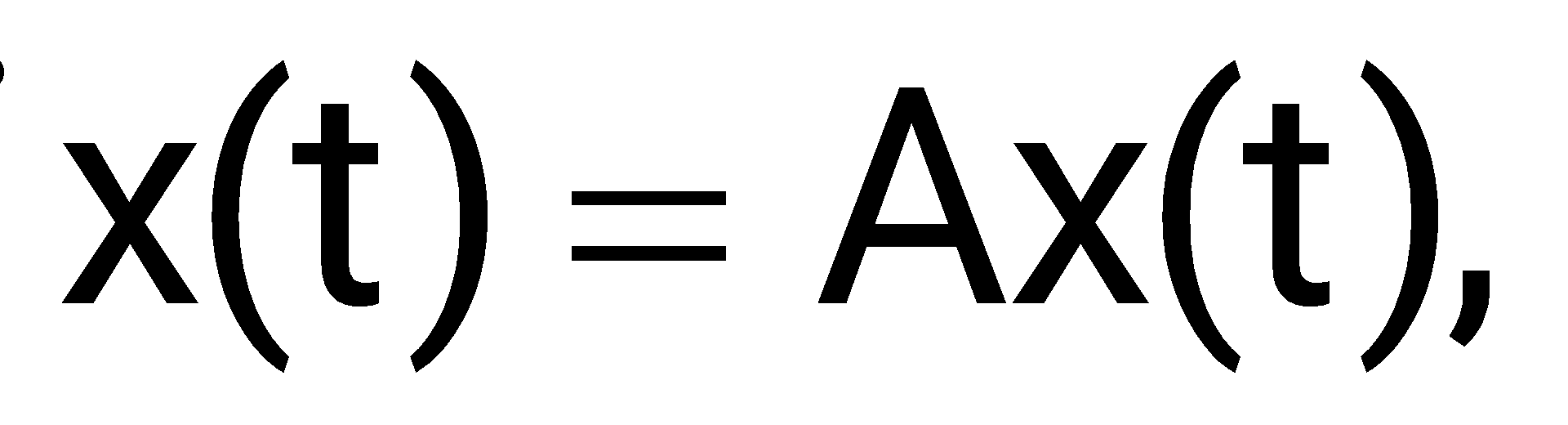
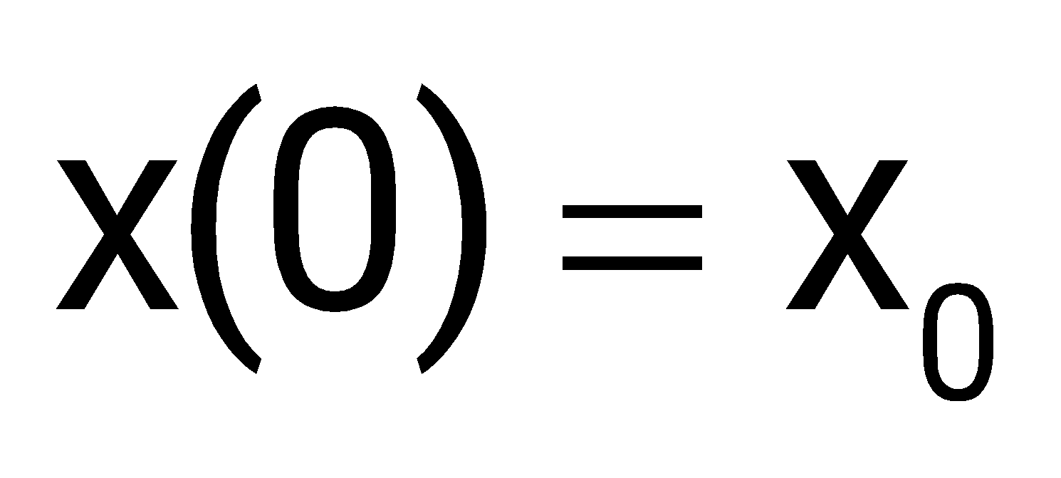
For and for
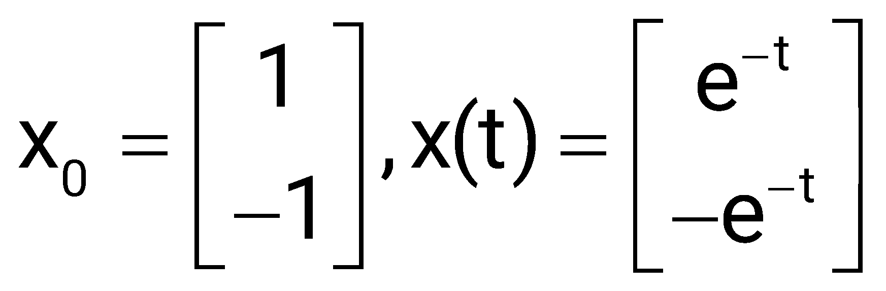
When , x(t) is
Sign in to see the solution
Log in to view the explanation, track your attempts, and keep your progress.
Sign in to UnlockThe state transition matrix of a system is
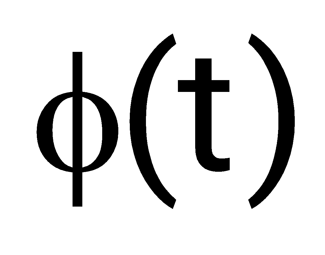
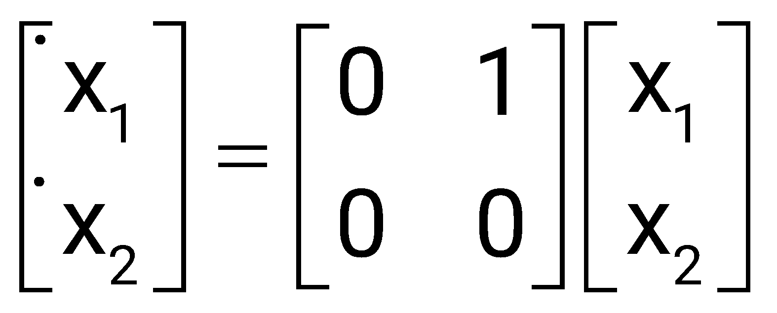
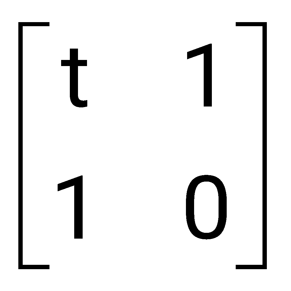
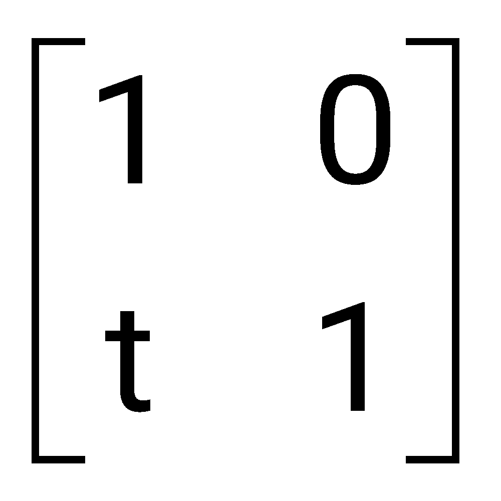
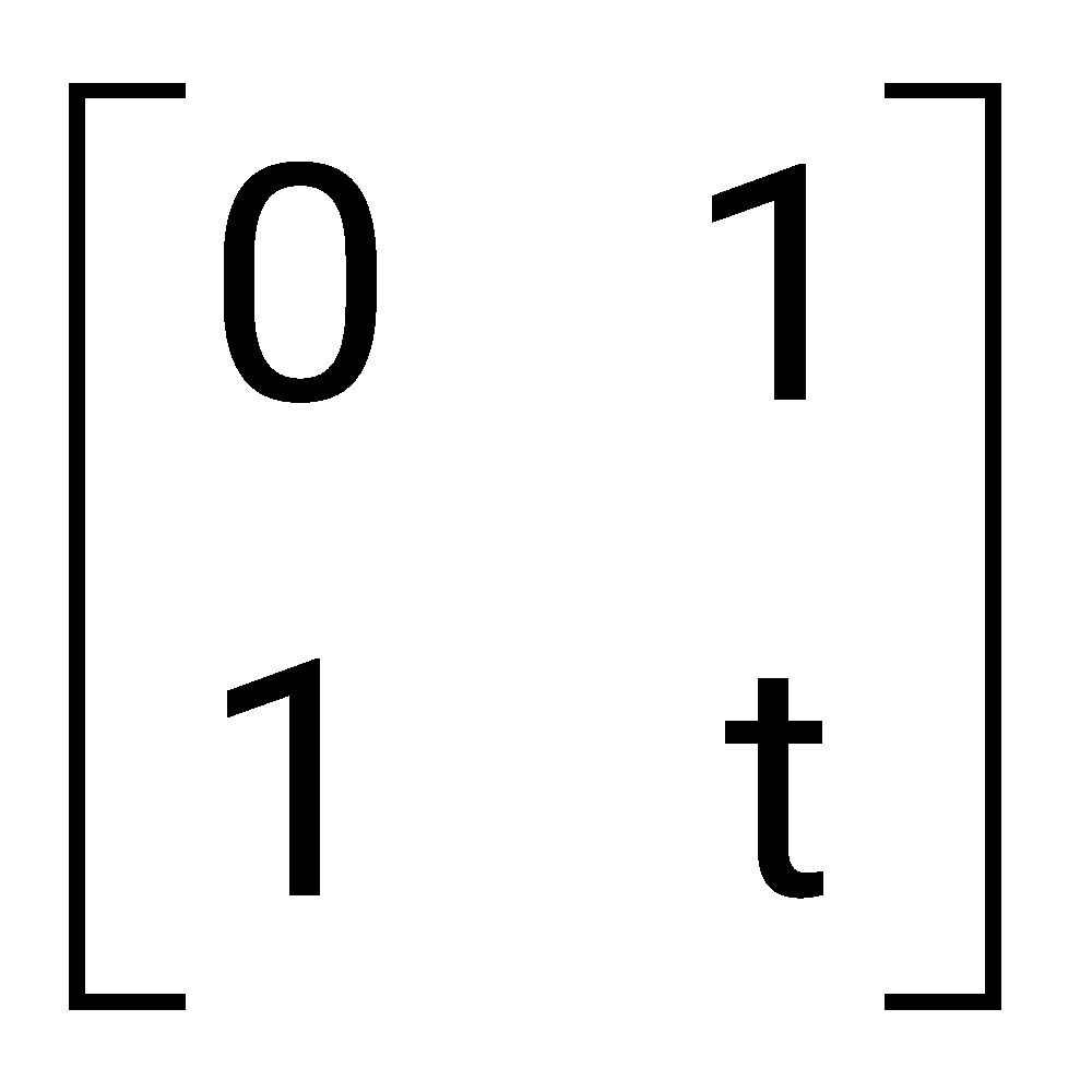
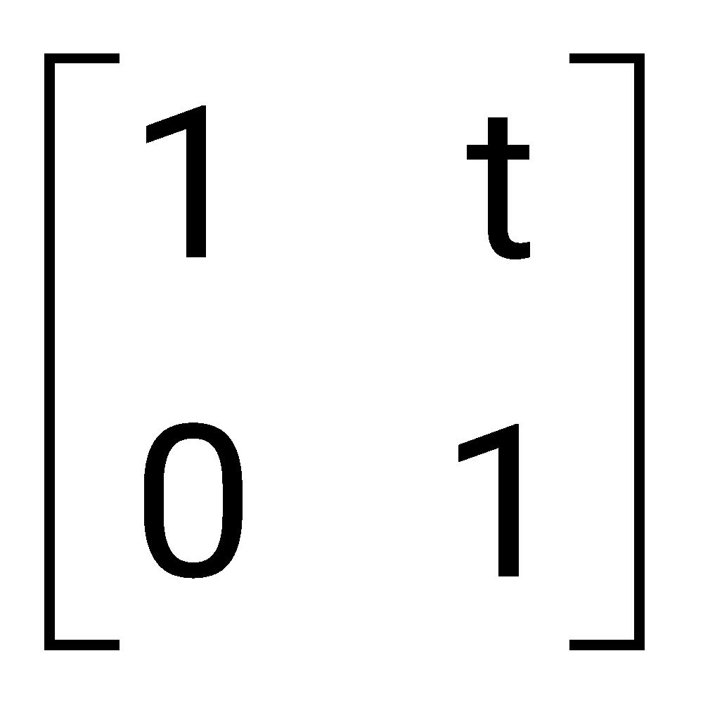
Sign in to see the solution
Log in to view the explanation, track your attempts, and keep your progress.
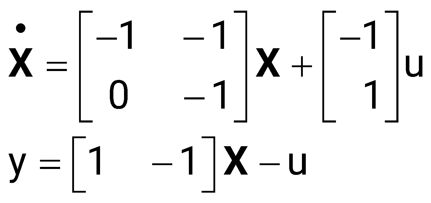
Sign in to UnlockThe state diagram of a system is shown below. A system is described by the state-variable equations
;
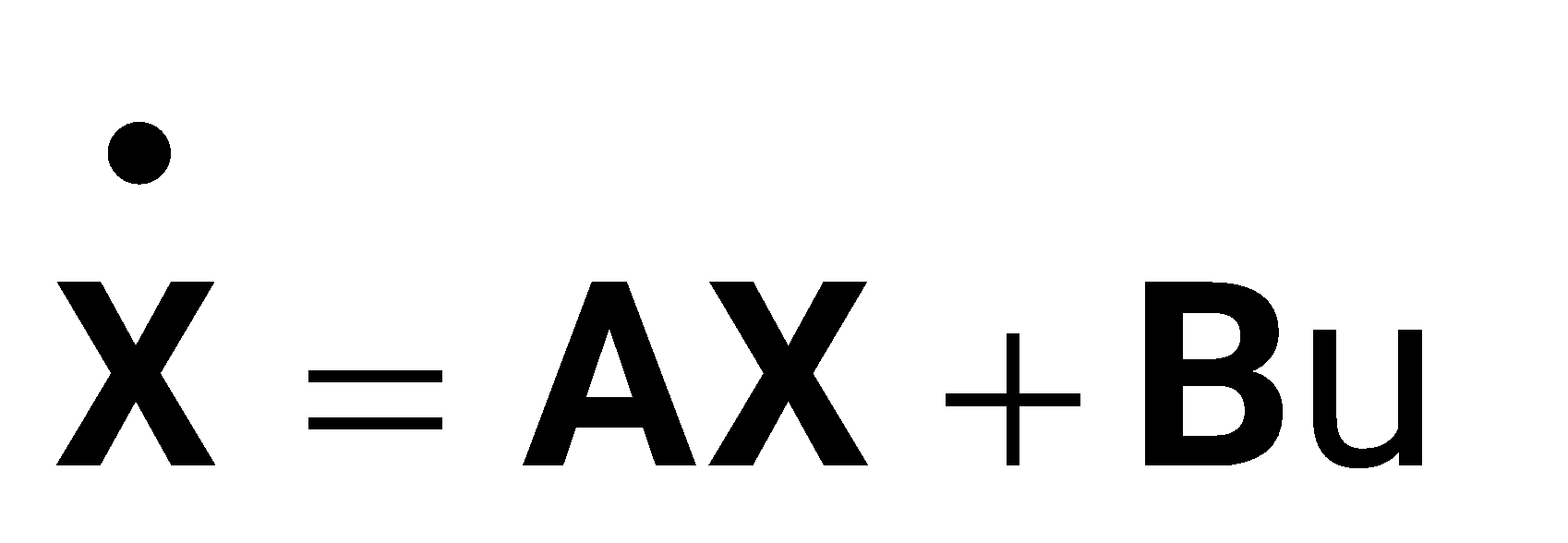
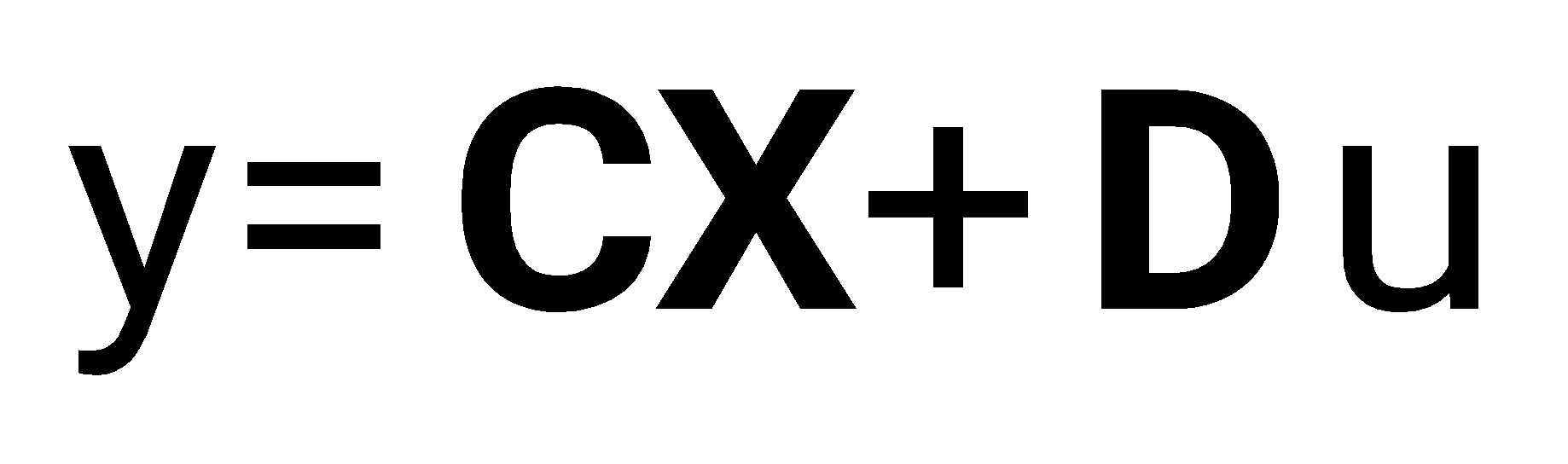
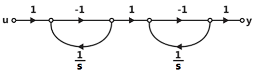
The state-variable equations of the system shown in the figure above are
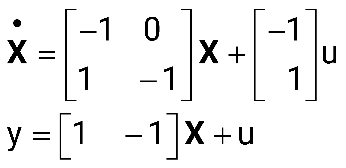
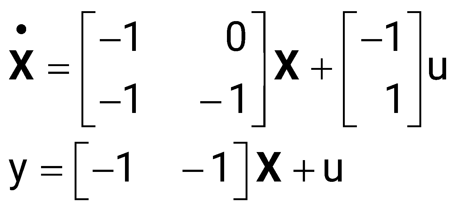
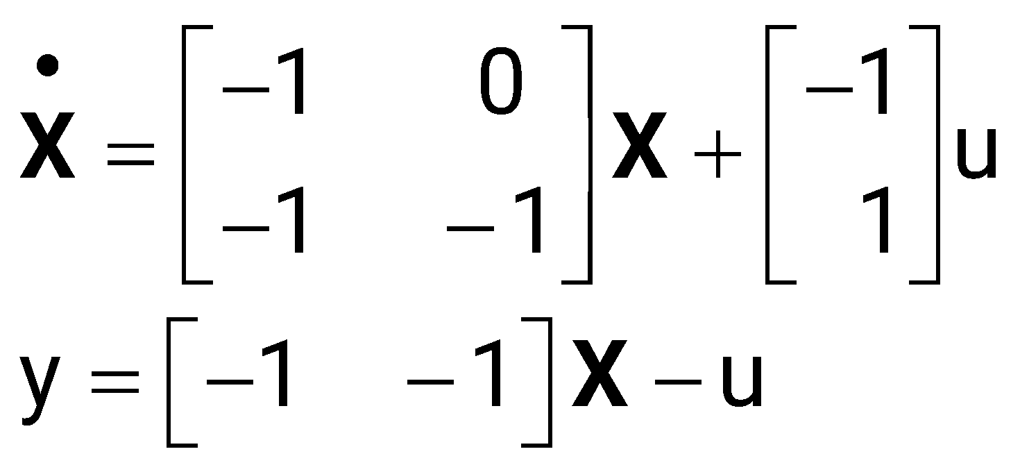
Sign in to see the solution
Log in to view the explanation, track your attempts, and keep your progress.
Sign in to UnlockThe state diagram of a system is shown below. A system is described by the state-variable equations
;
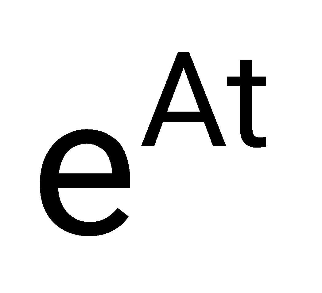
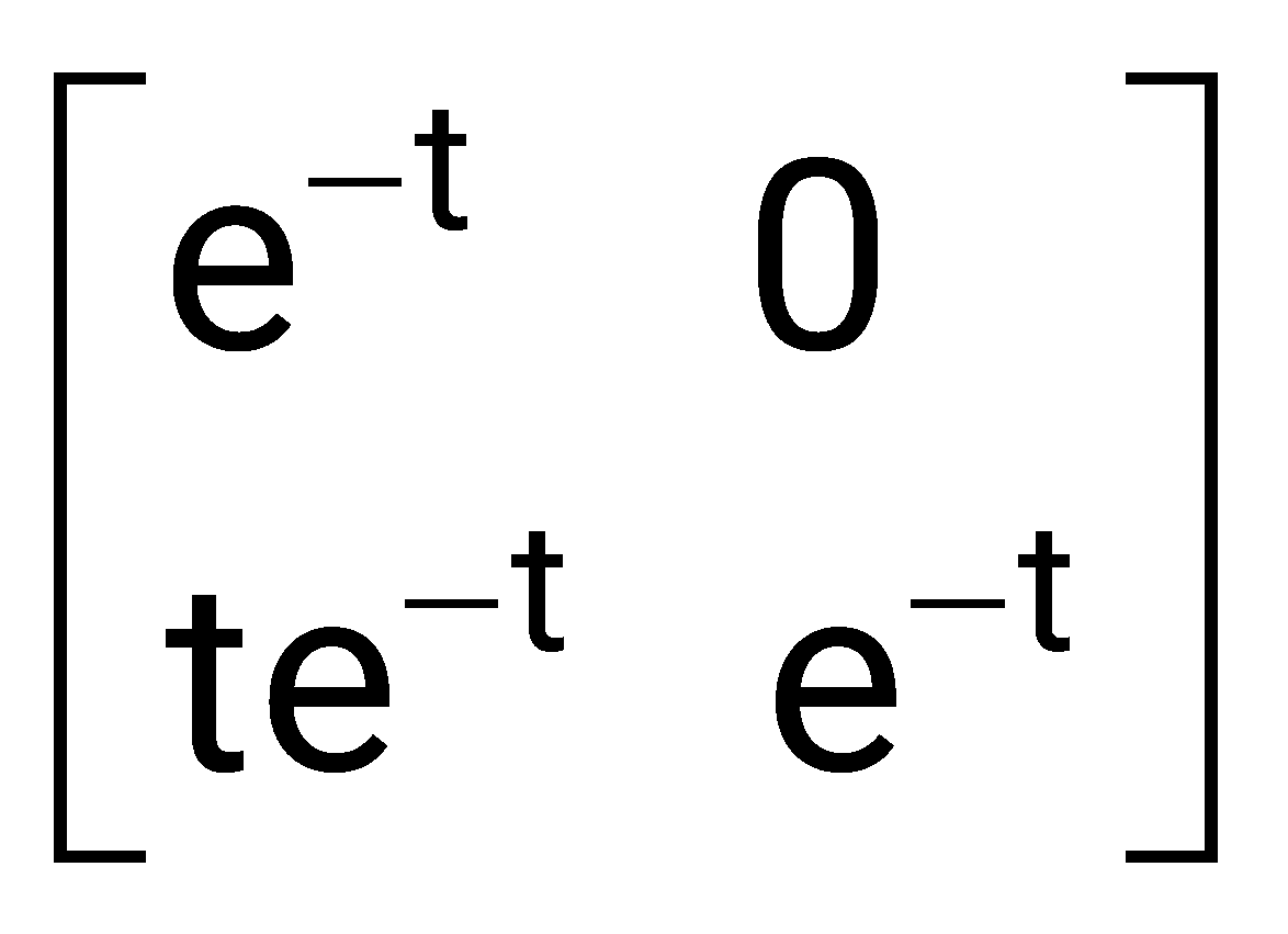
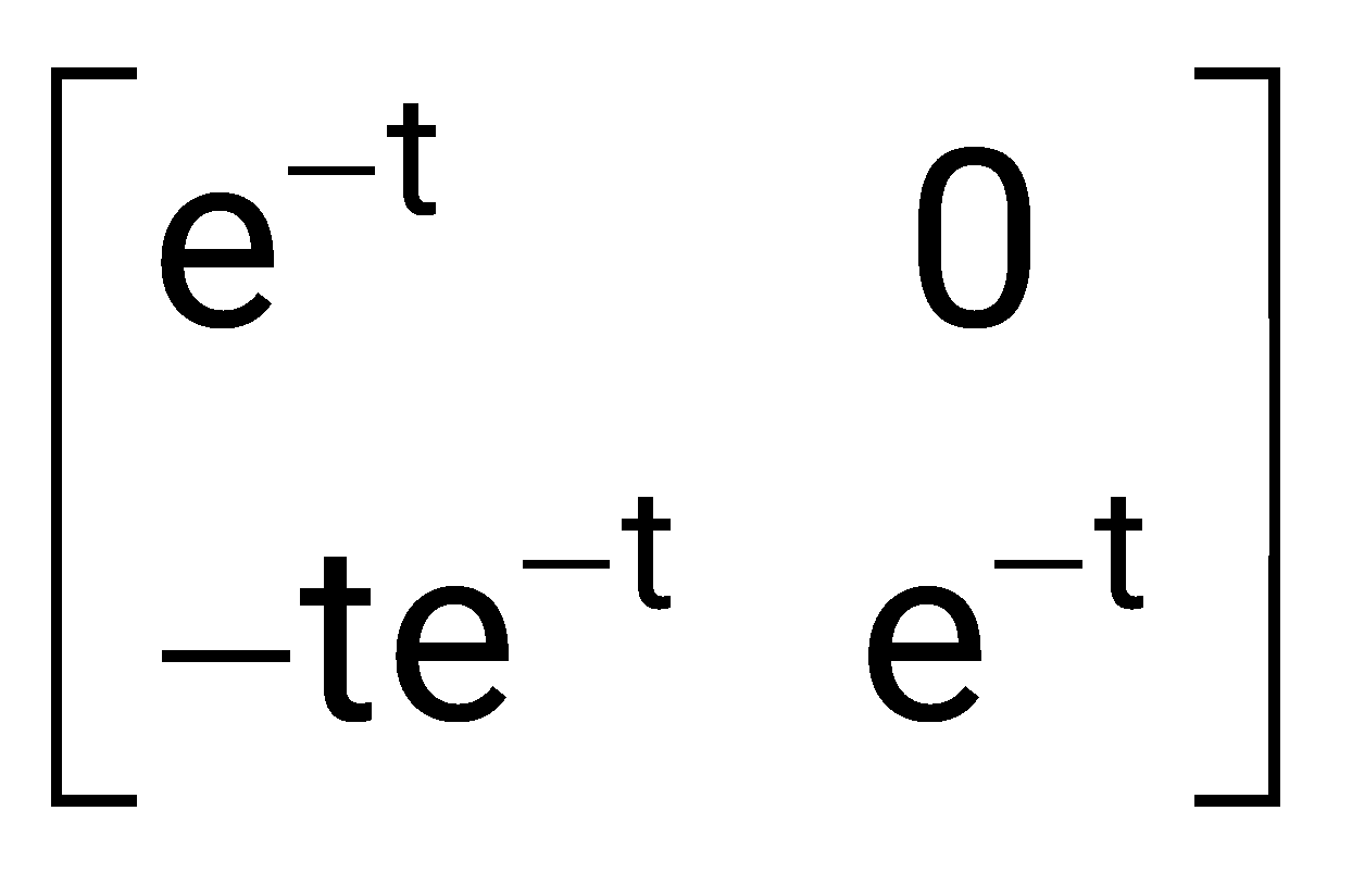
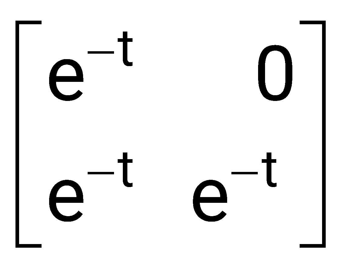
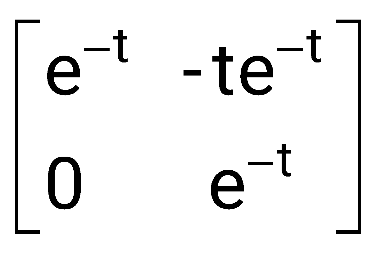
The state transition matrix of the system shown in the figure above is
Sign in to see the solution
Log in to view the explanation, track your attempts, and keep your progress.
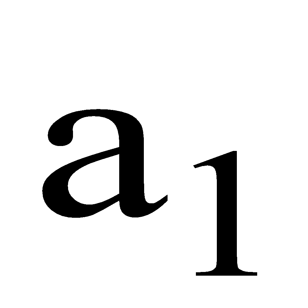
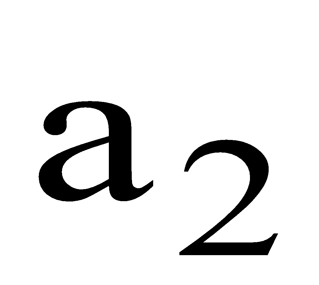
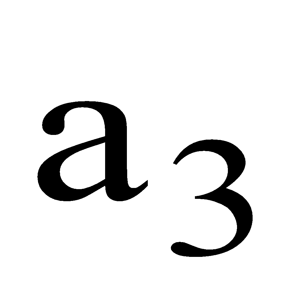
Sign in to UnlockThe state variable description of an LTI system is given by
and
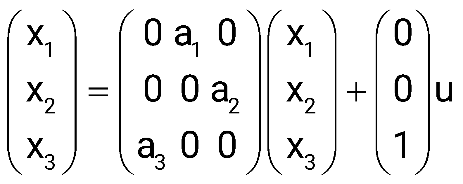
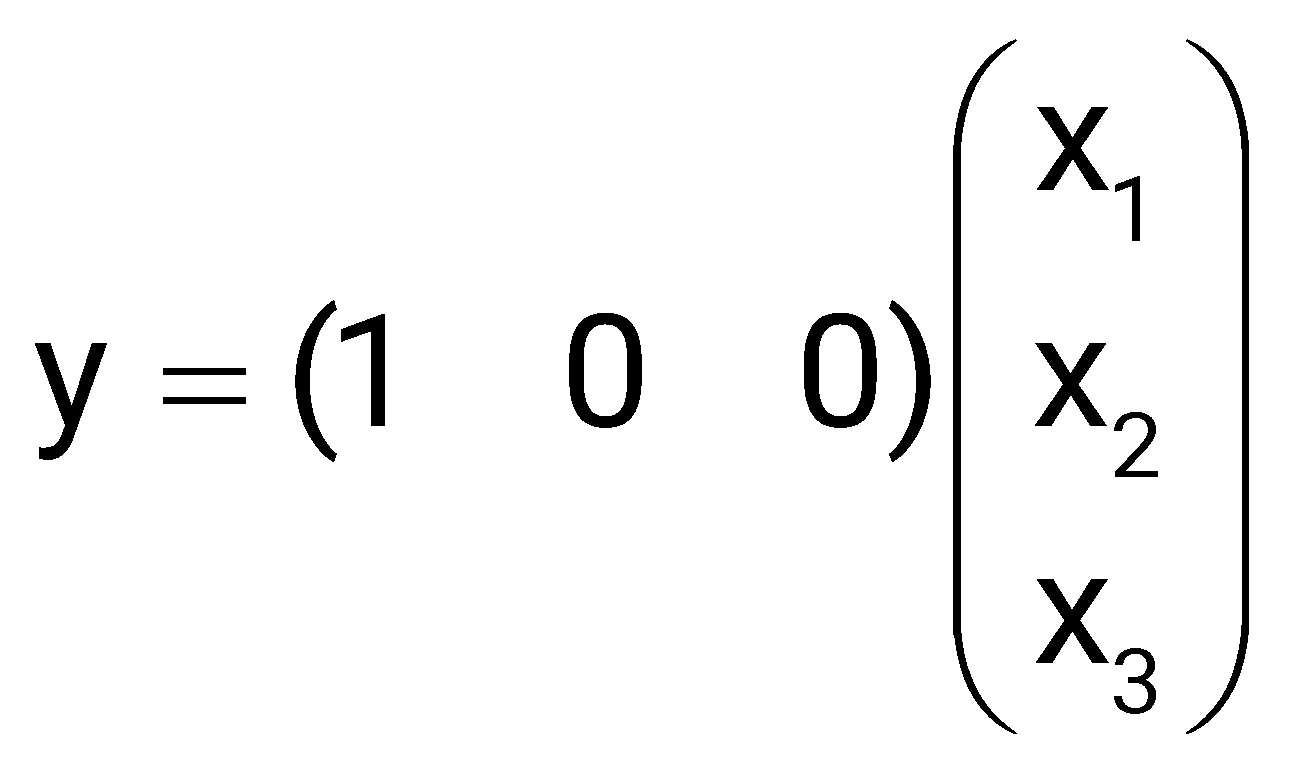
Where y is the output and u is the input. The system is controllable for
≠ 0, =0, ≠ 0
= 0, ≠0, ≠0
=0, ≠0, =0
≠0, ≠0, ≠0
Sign in to see the solution
Log in to view the explanation, track your attempts, and keep your progress.
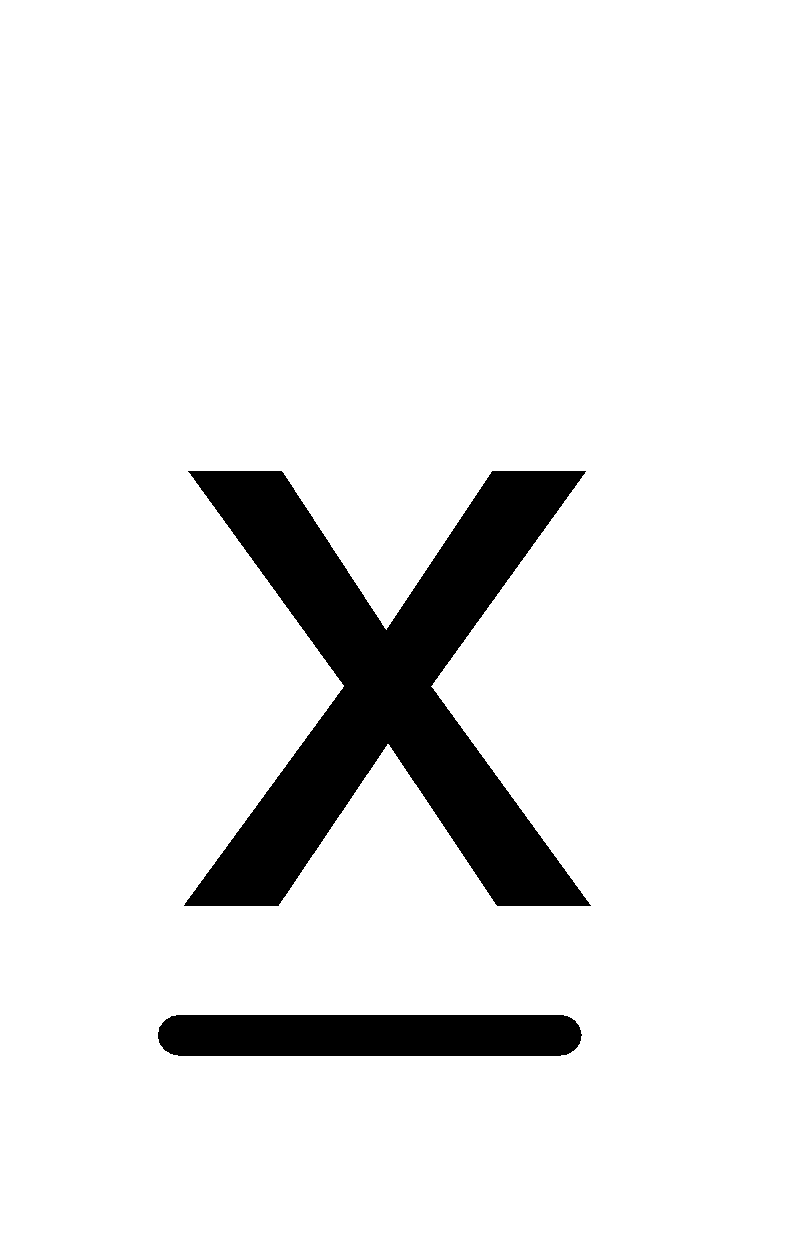
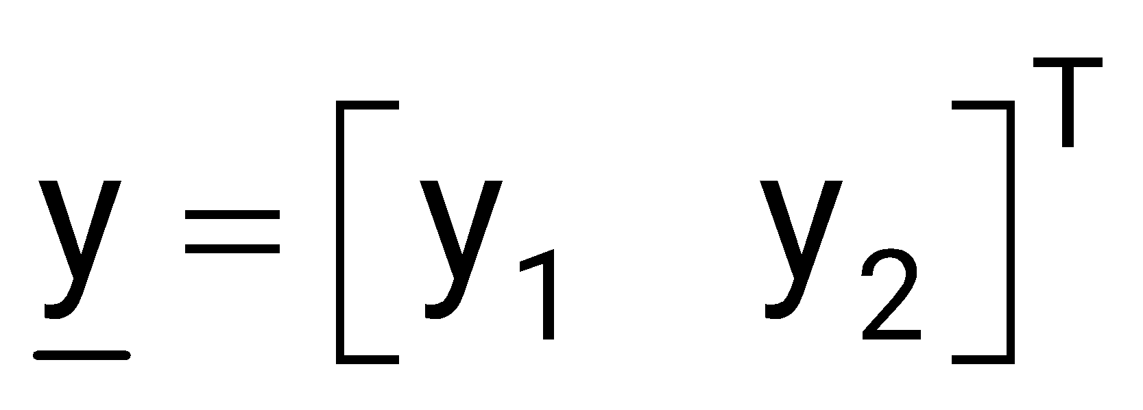
Sign in to UnlockThe block diagram of a system with one input u and two outputs and is given below.
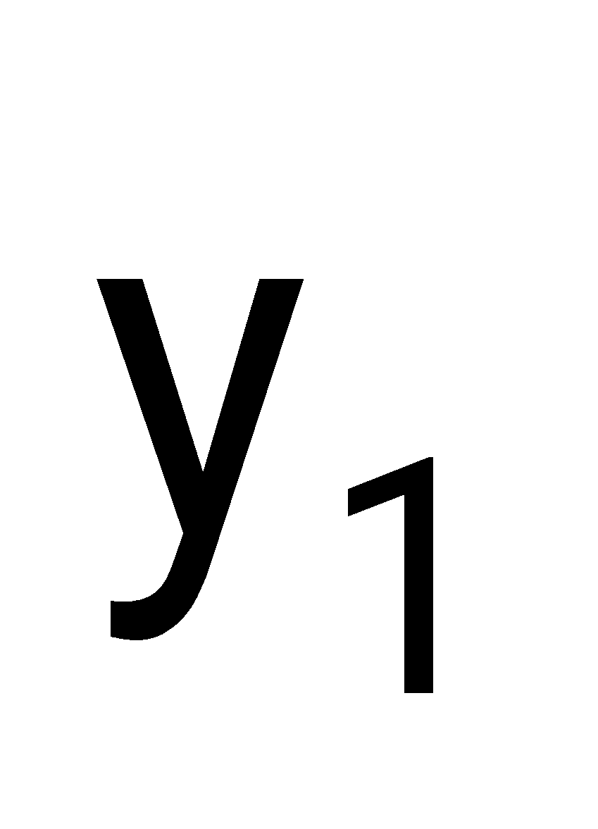
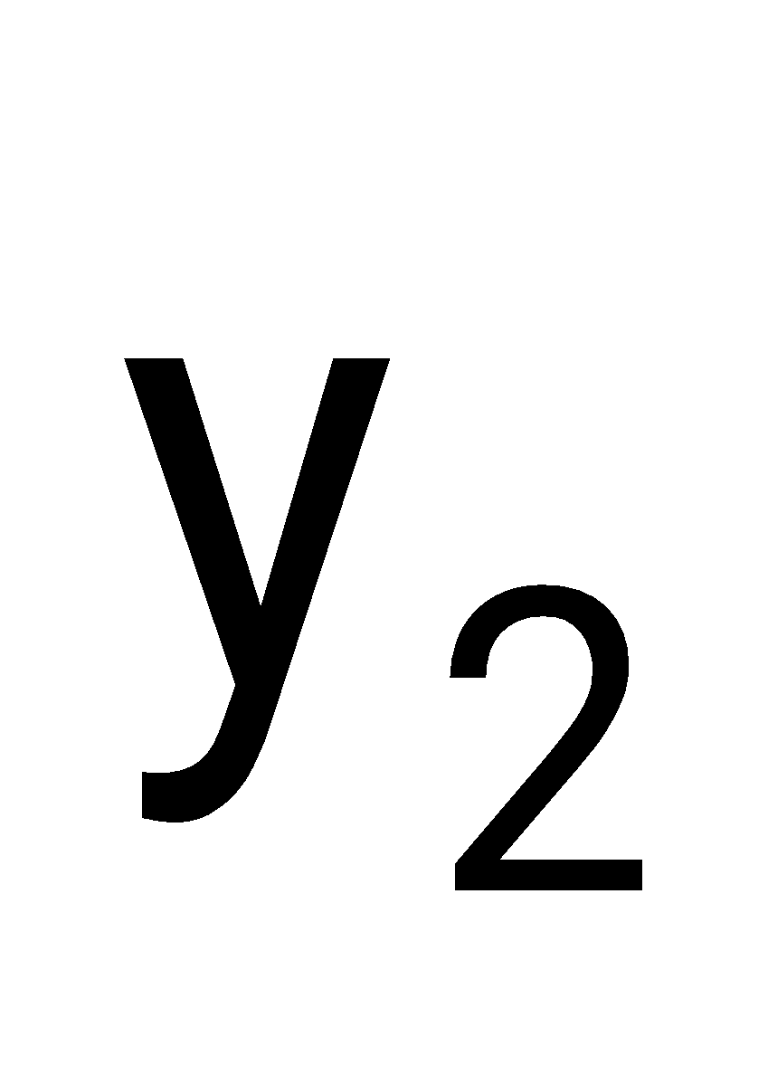
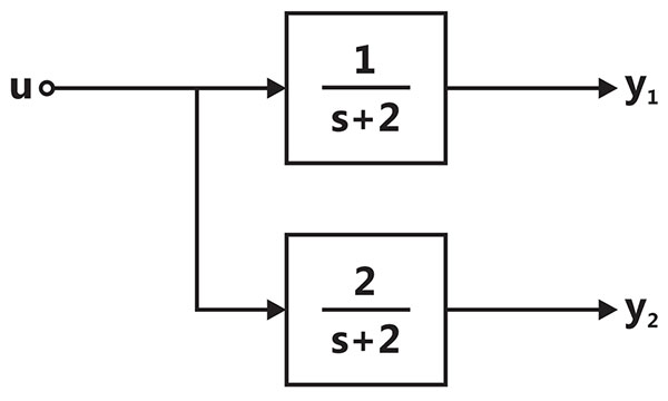
A state space model of the above system in terms of the state vector and the output vector is
;
;
;
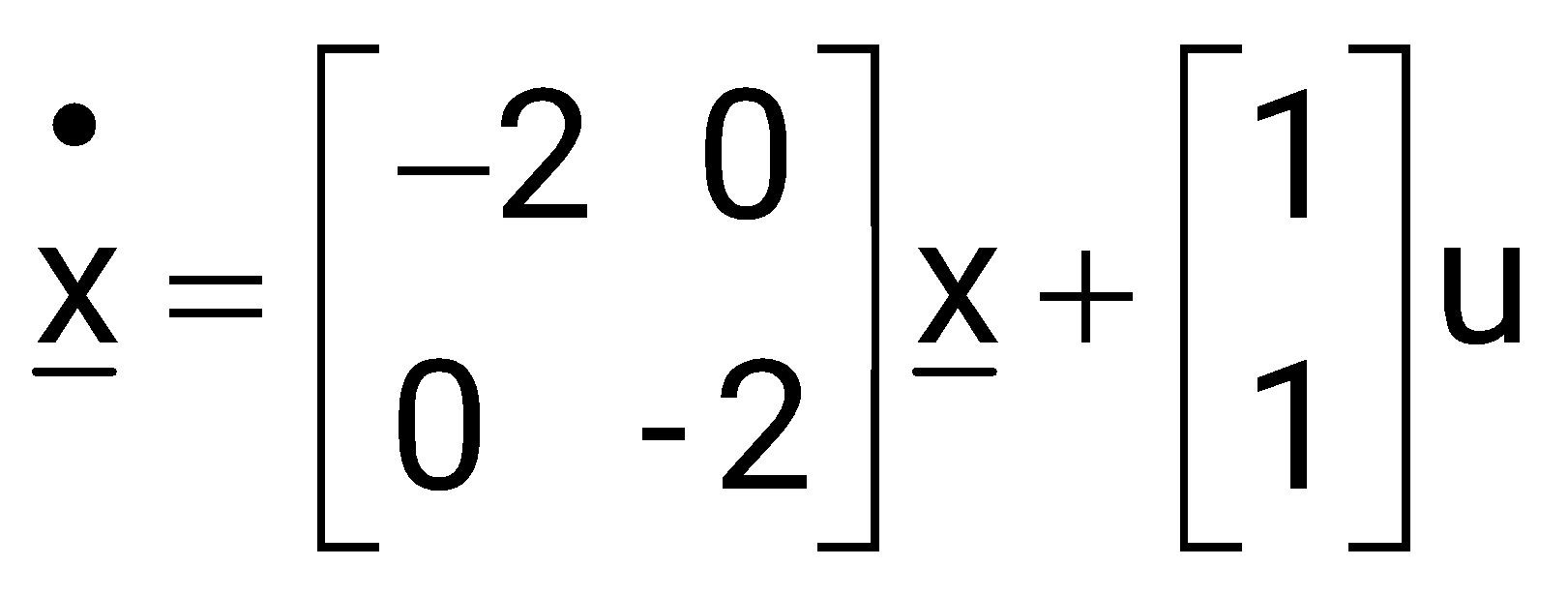
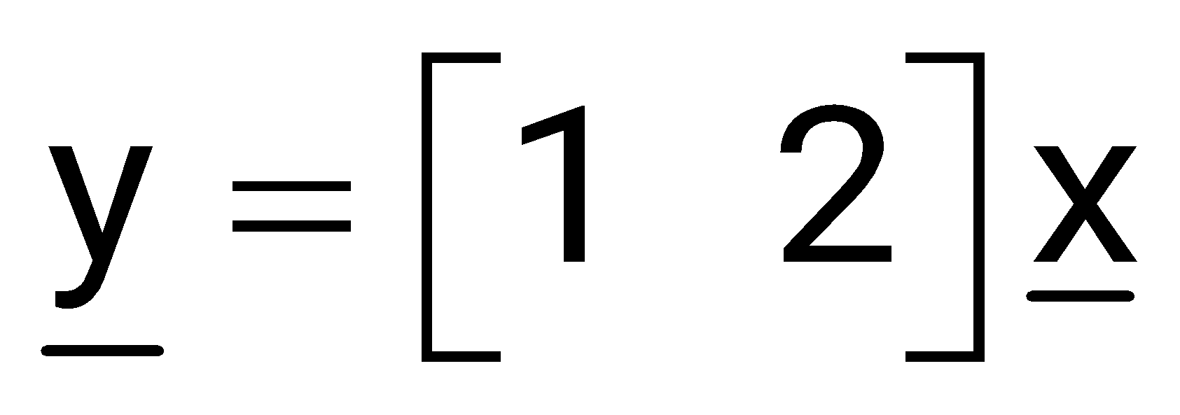
;
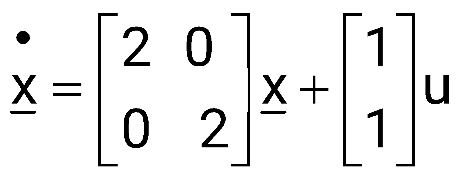
Sign in to see the solution
Log in to view the explanation, track your attempts, and keep your progress.
Sign in to UnlockThe signal flow graph of a system is shown below.
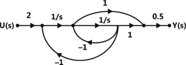
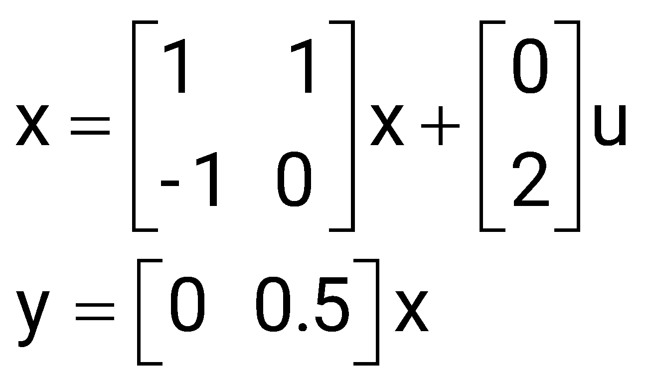
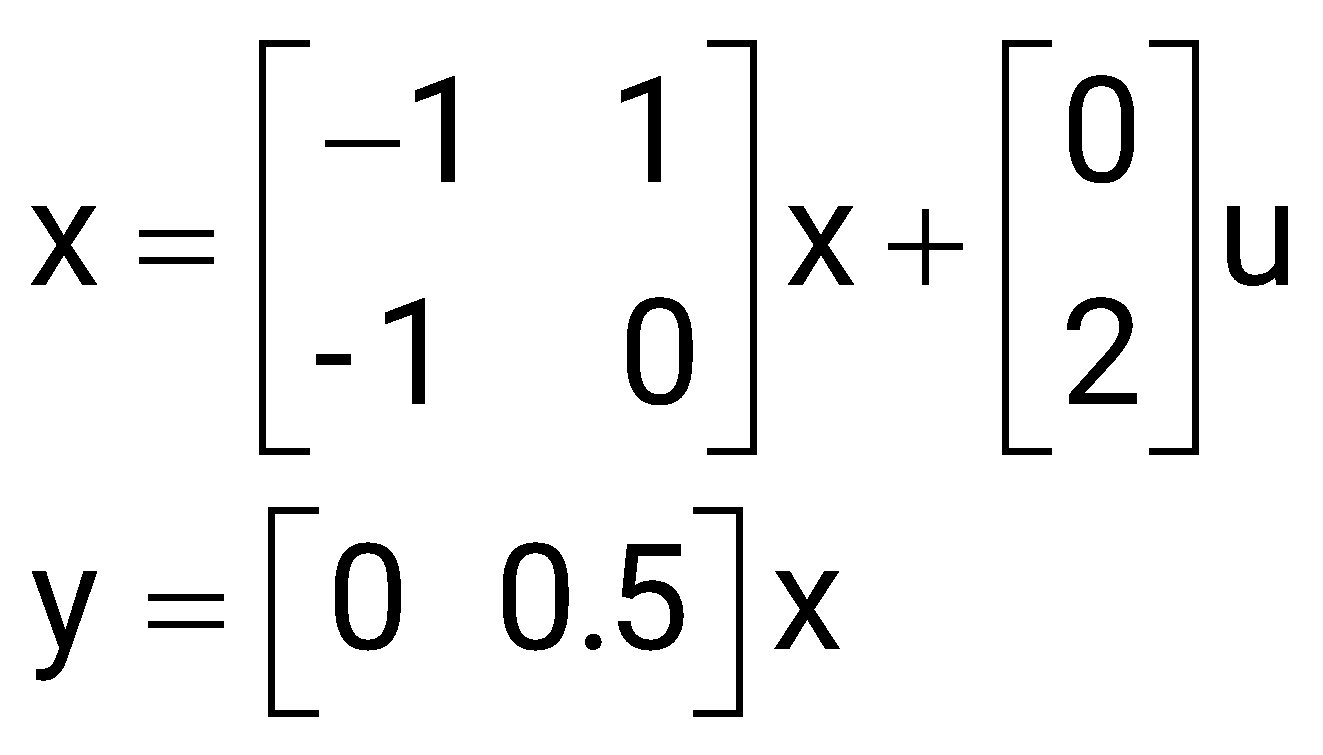
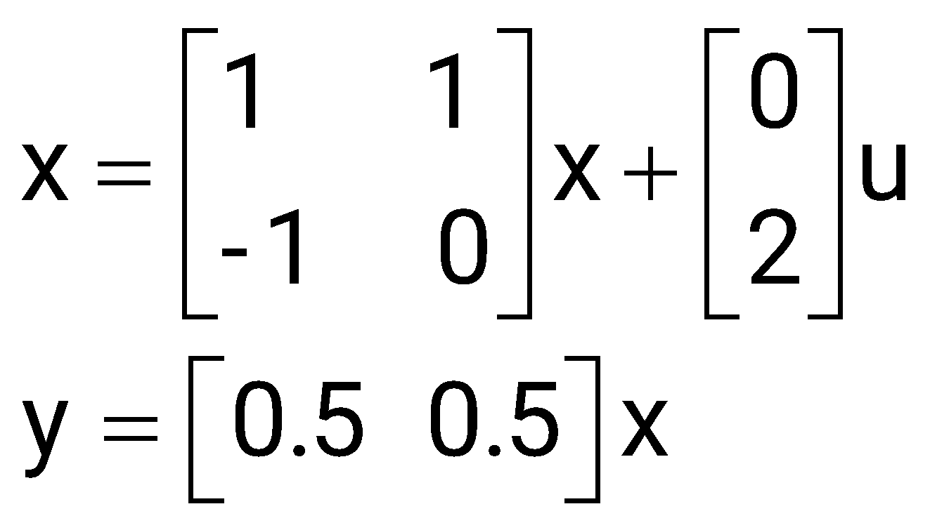
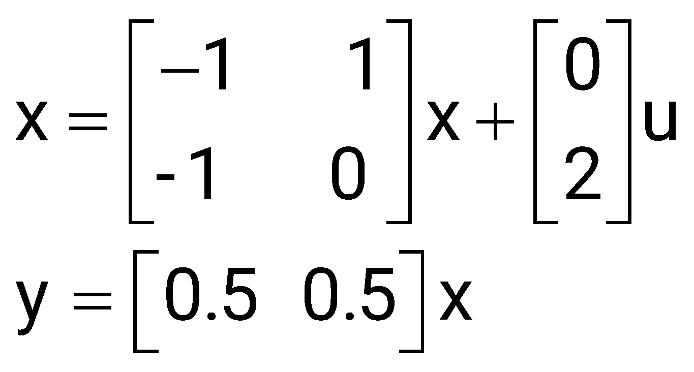
The state variable representation of the system can be
Sign in to see the solution
Log in to view the explanation, track your attempts, and keep your progress.
Sign in to UnlockThe signal flow graph of a system is shown below.
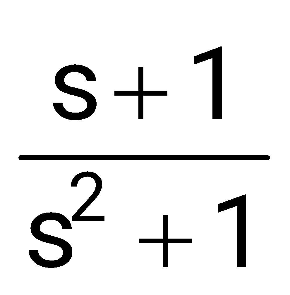
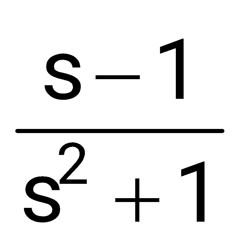
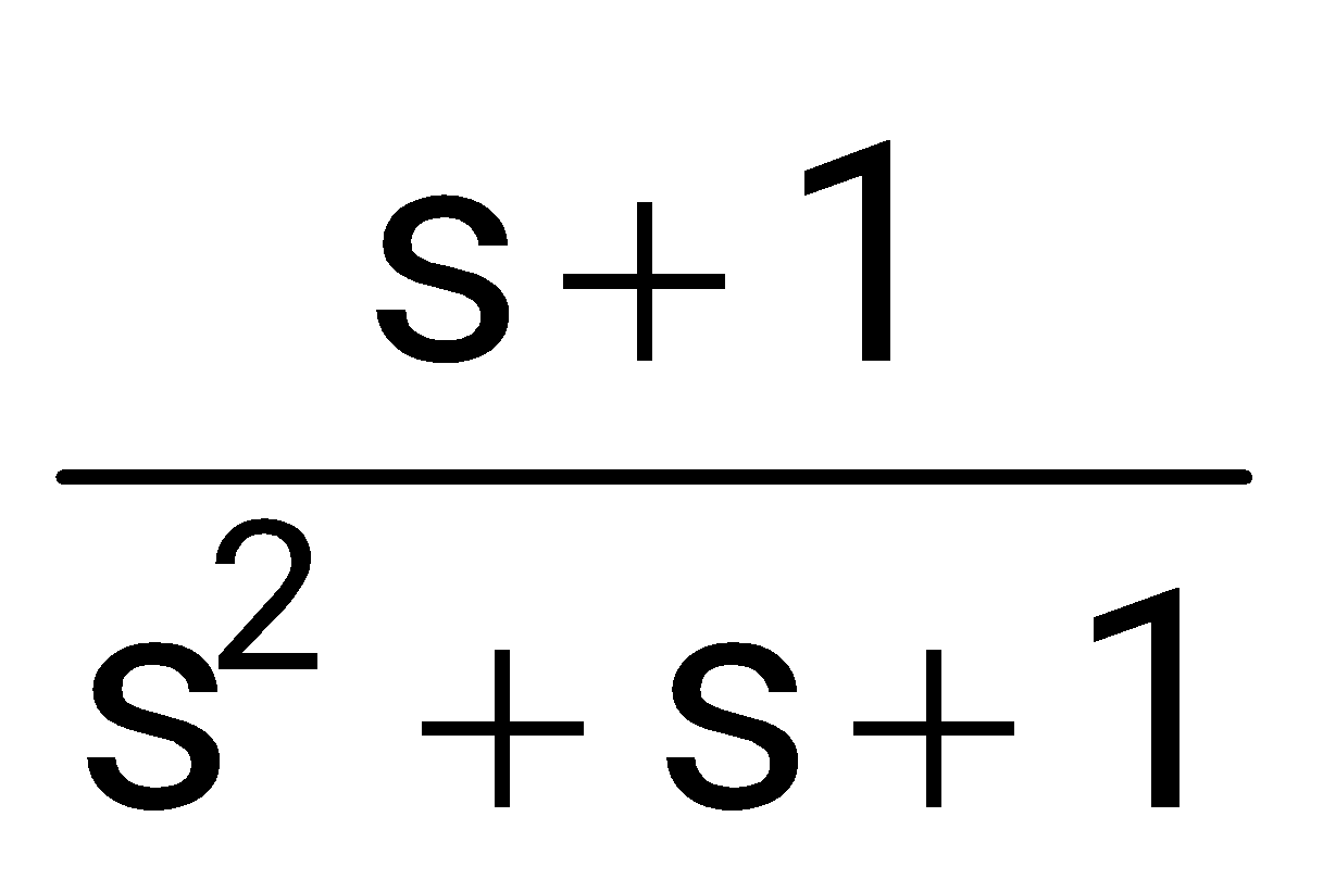
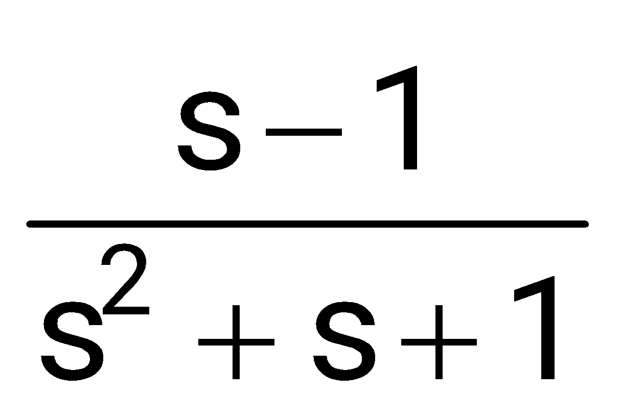
The transfer function of the system is
Sign in to see the solution
Log in to view the explanation, track your attempts, and keep your progress.
Sign in to UnlockConsider the system with and where p and q are arbitrary real numbers. Which of the following statements about the controllability of the system is true?
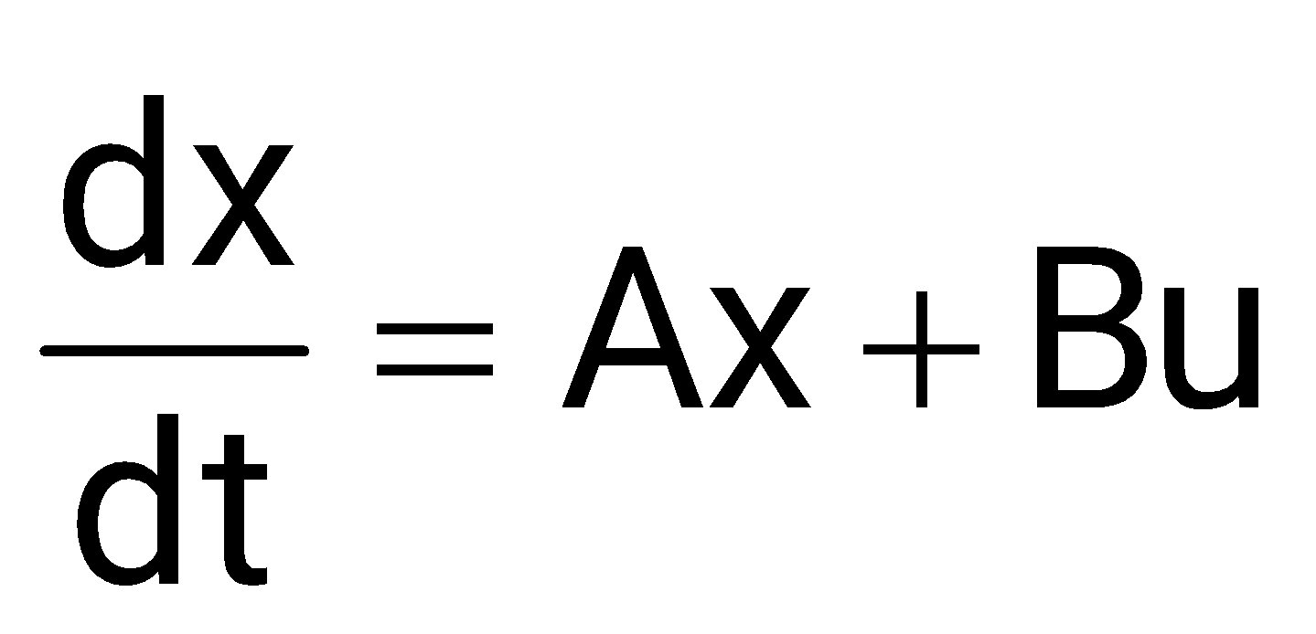
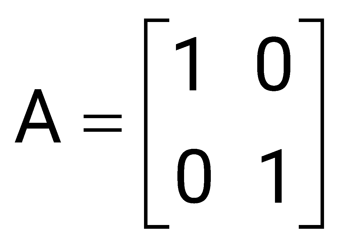
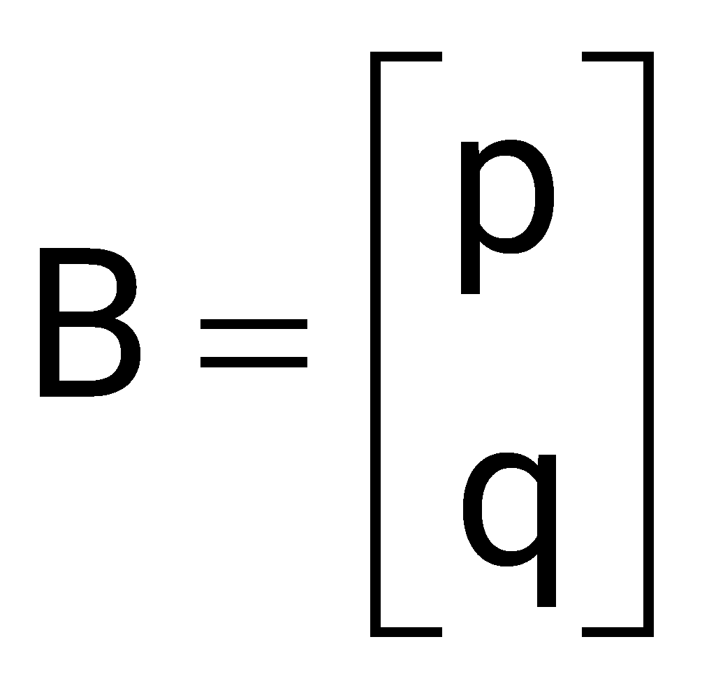
Sign in to see the solution
Log in to view the explanation, track your attempts, and keep your progress.
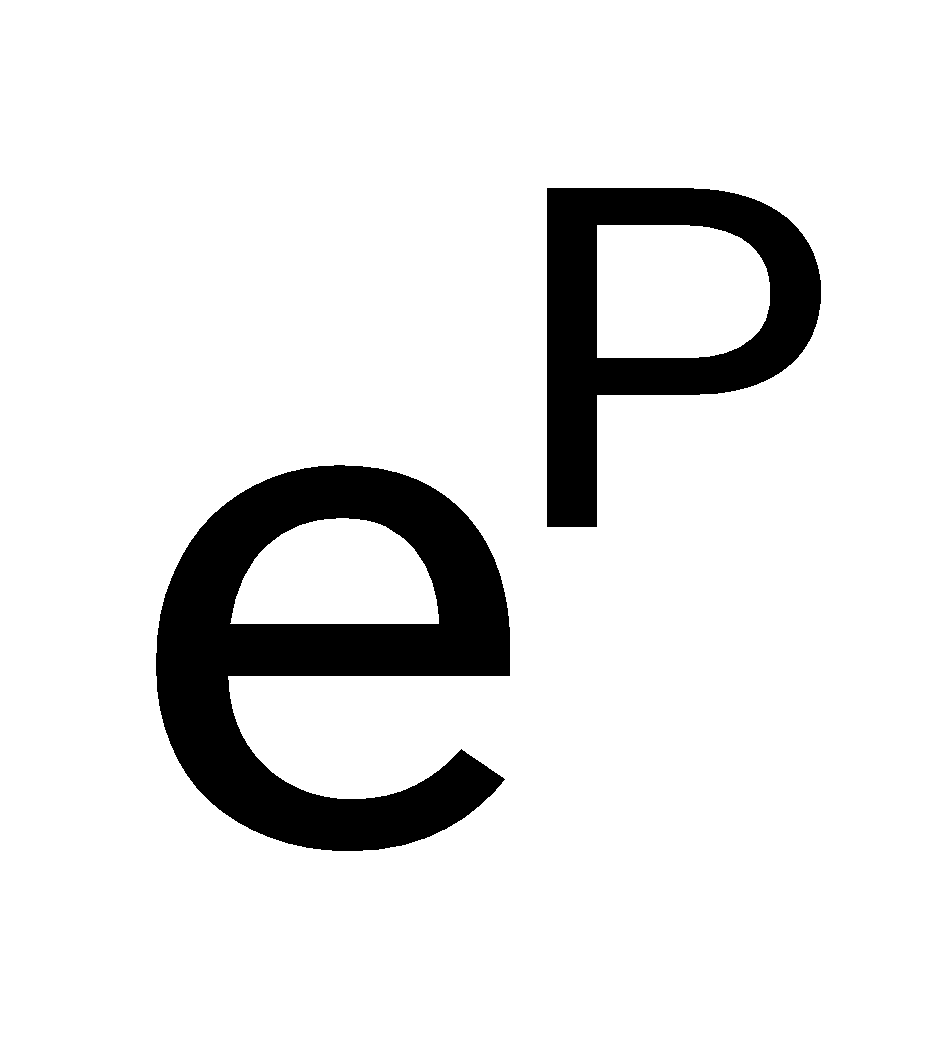
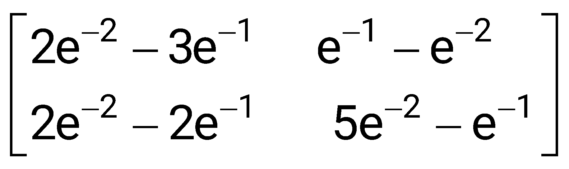
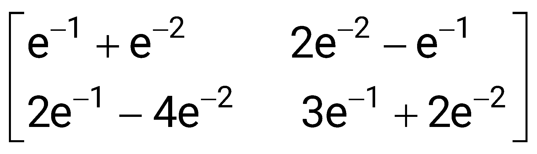
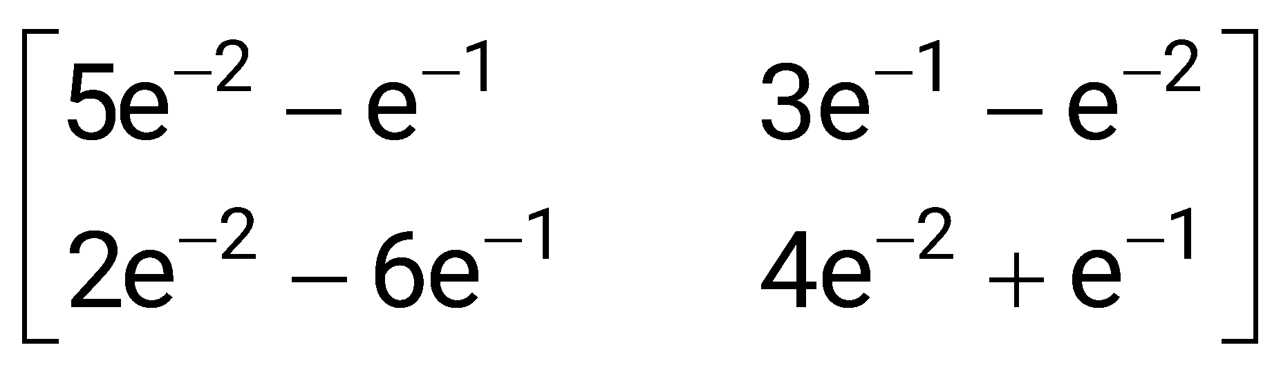
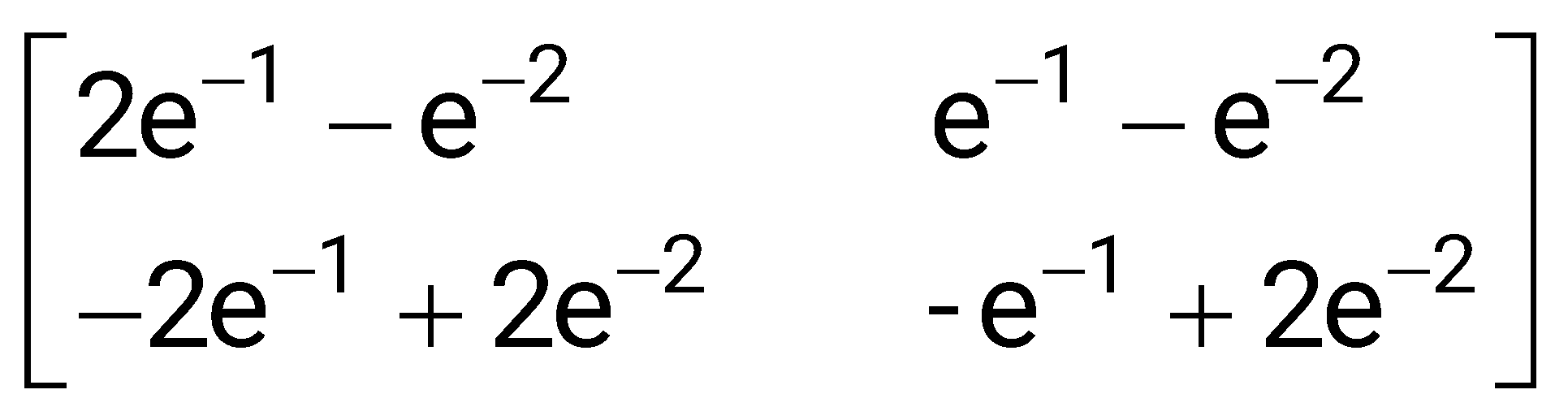
Sign in to UnlockConsider the matrix . The value of is
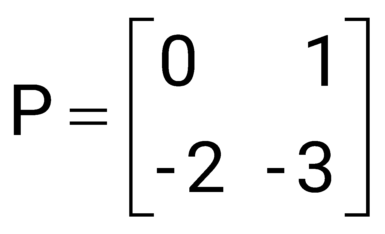
Sign in to see the solution
Log in to view the explanation, track your attempts, and keep your progress.
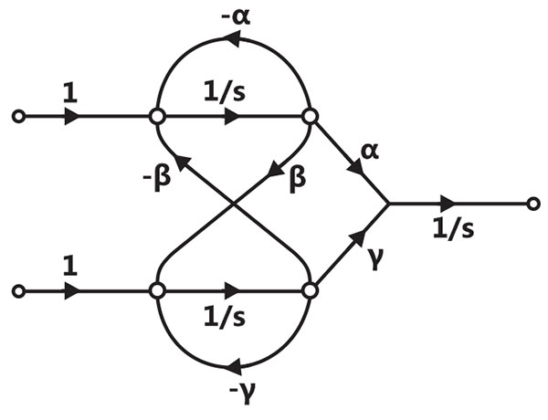
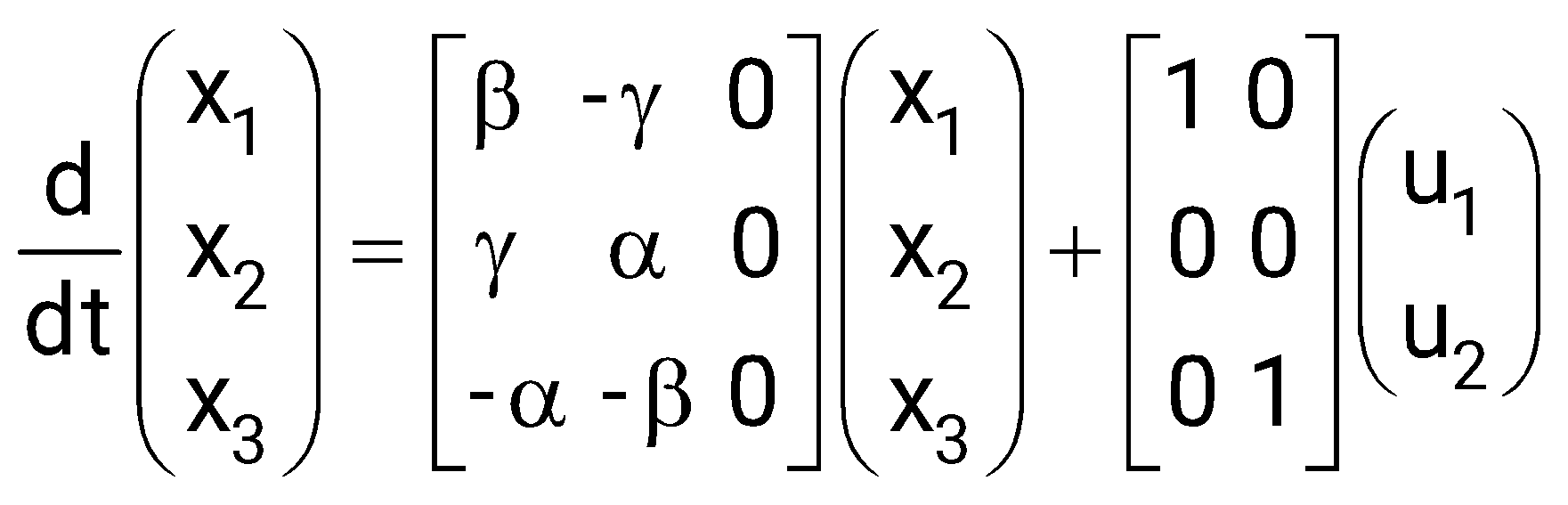
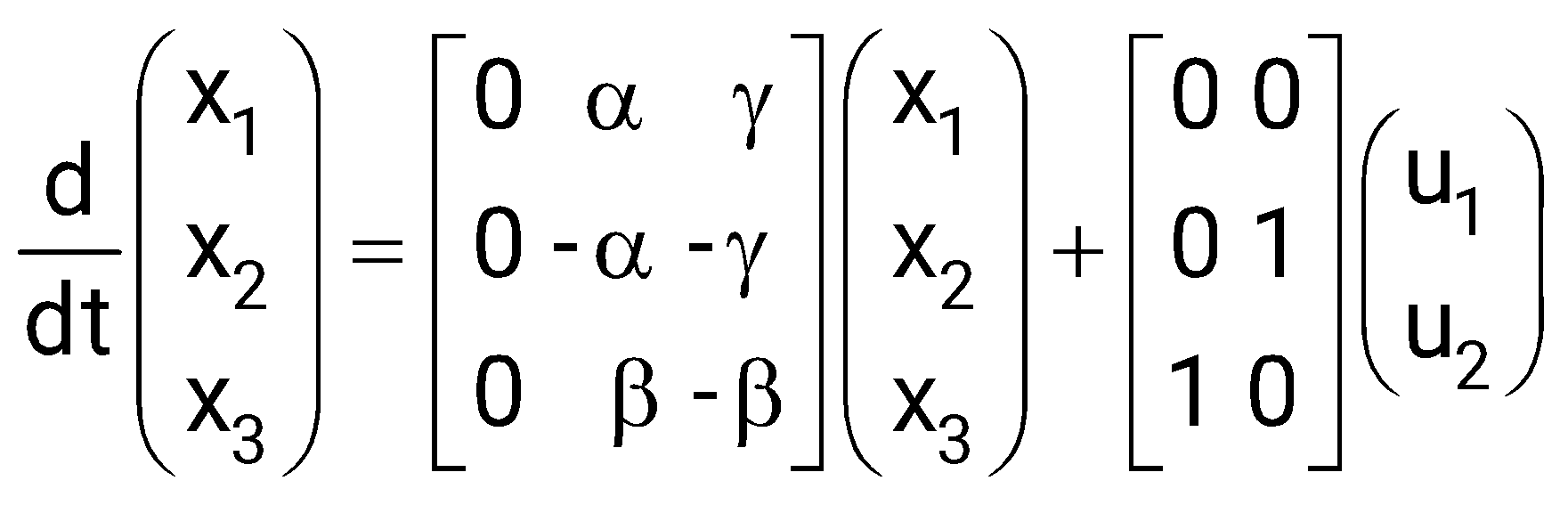
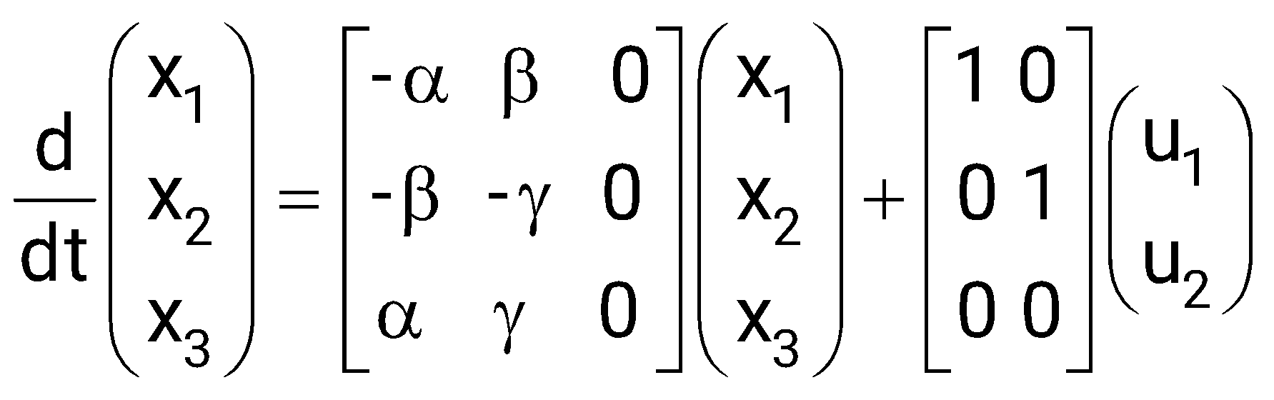
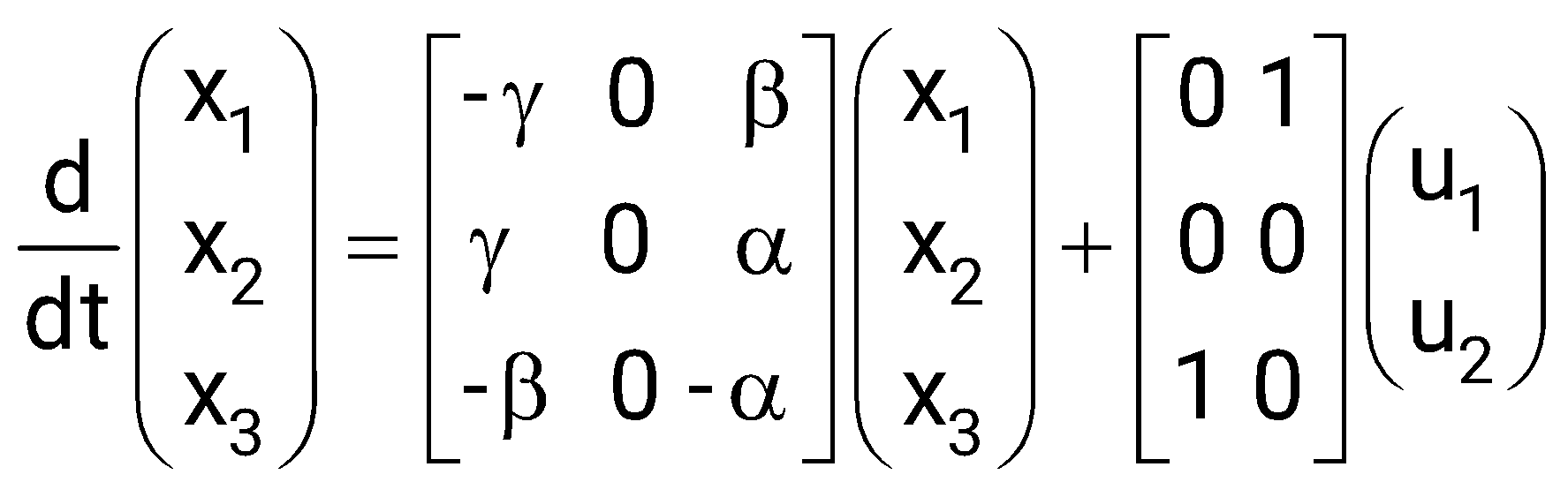
Sign in to UnlockA signal flow graph of a system is given below. The set of equations that correspond to this signal flow graph is
Sign in to see the solution
Log in to view the explanation, track your attempts, and keep your progress.
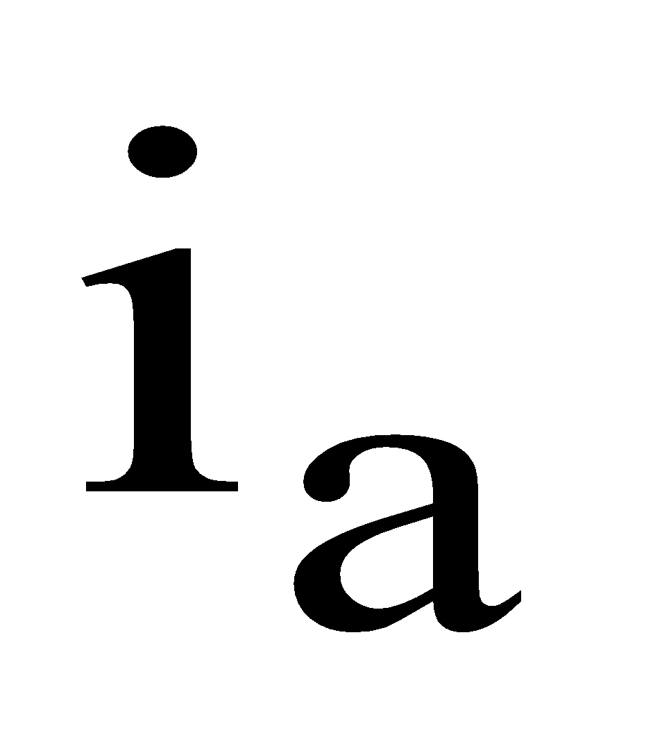
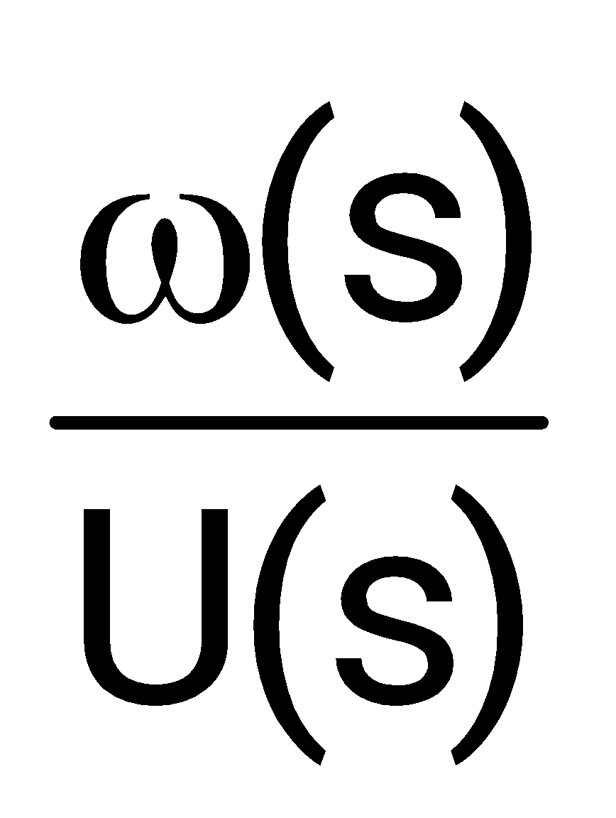
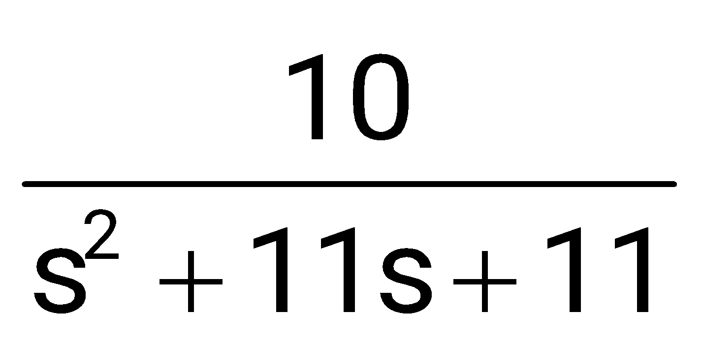
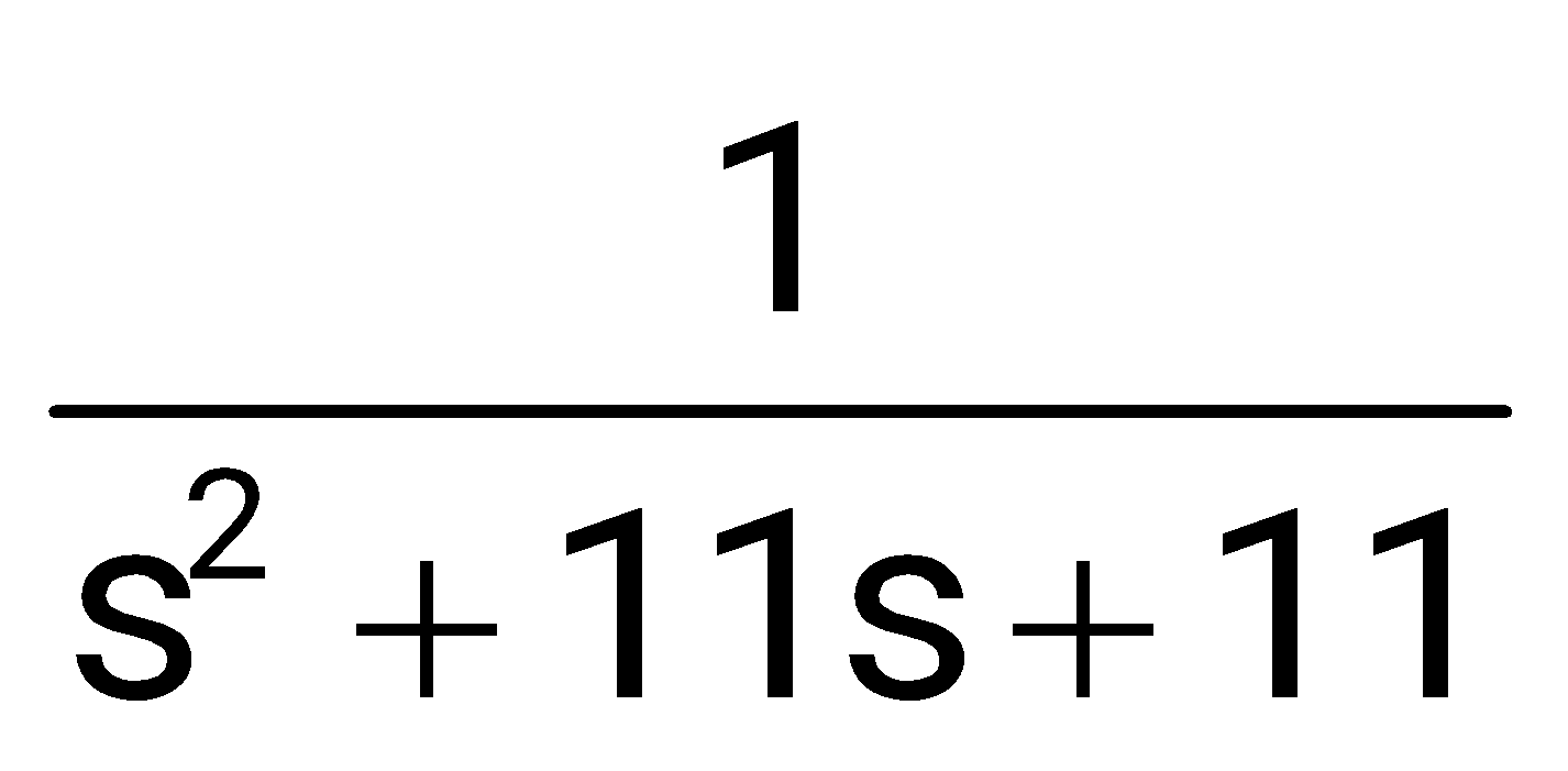
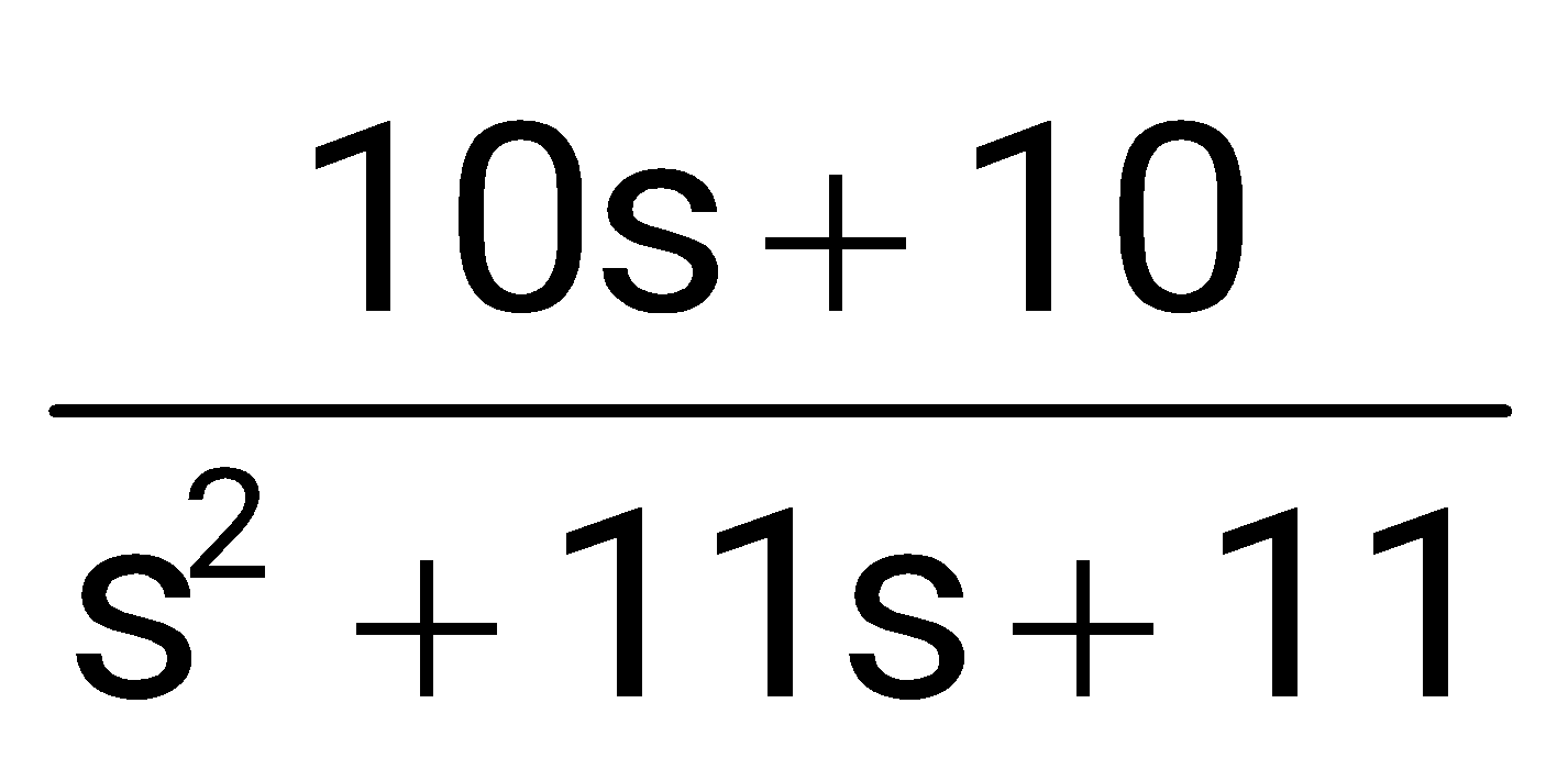
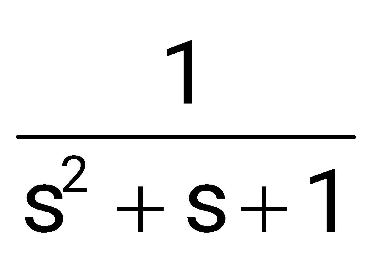
Sign in to UnlockThe state space representation of a separately excited DC servo motor dynamics is given as
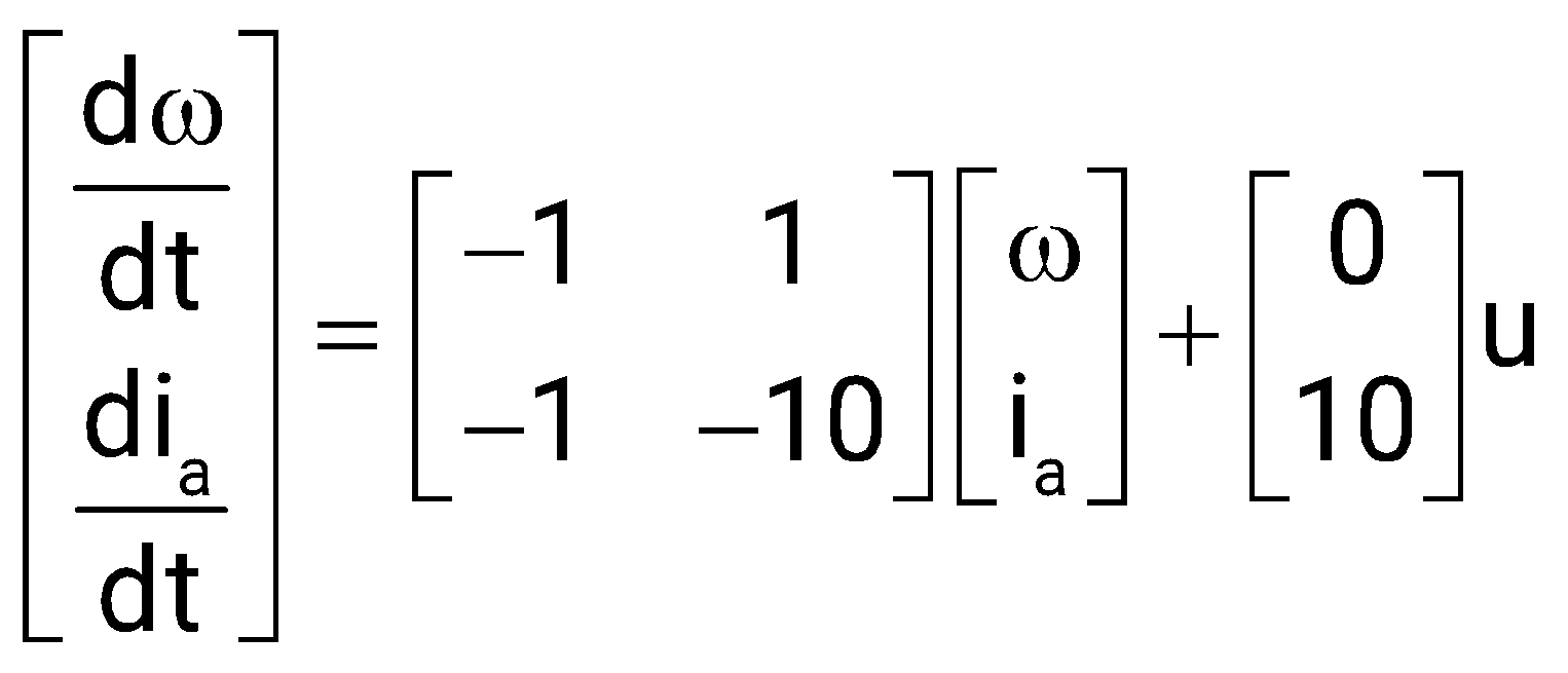
Where ω is the speed of the motor, is the armature current and u is the armature voltage. The transfer function of the motor is
Sign in to see the solution
Log in to view the explanation, track your attempts, and keep your progress.
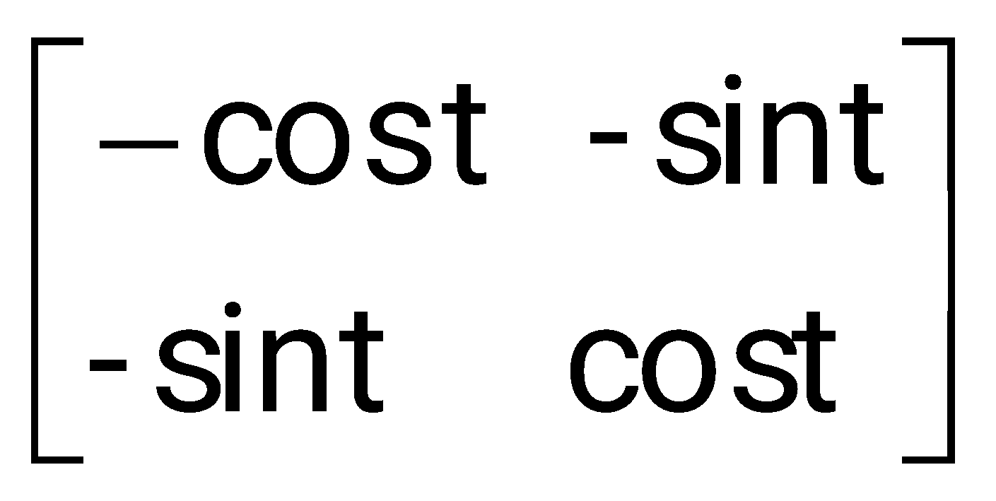
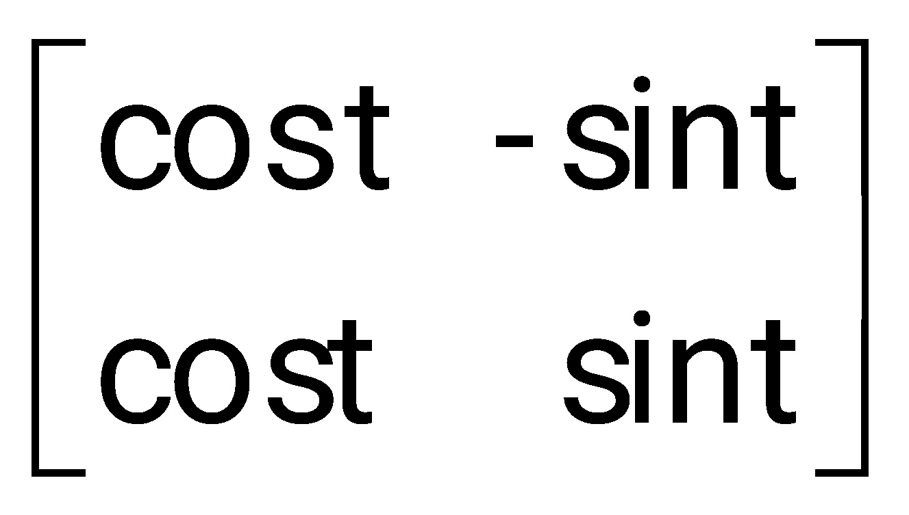
Sign in to UnlockA linear system is described by the following state equation
, .

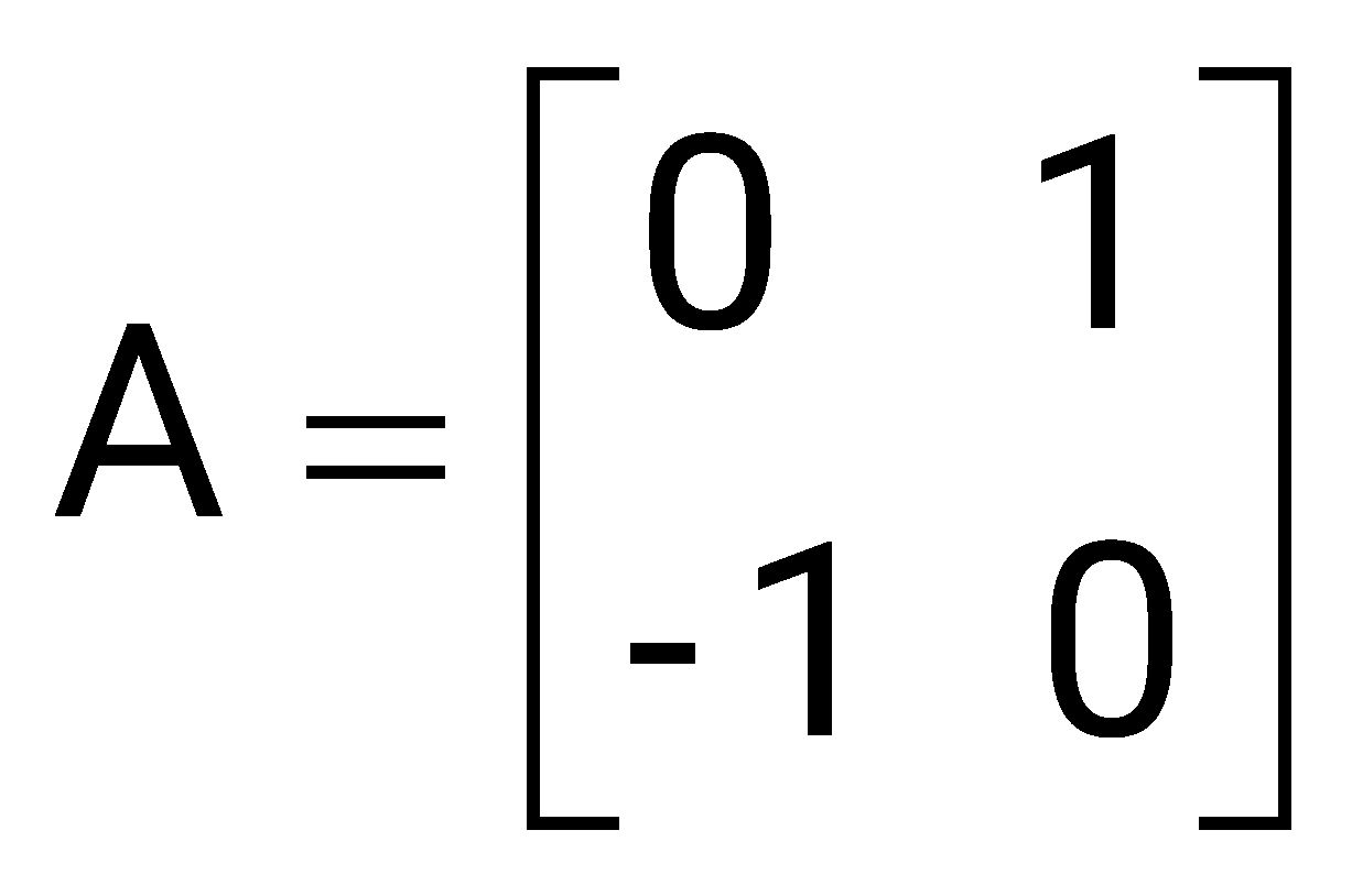
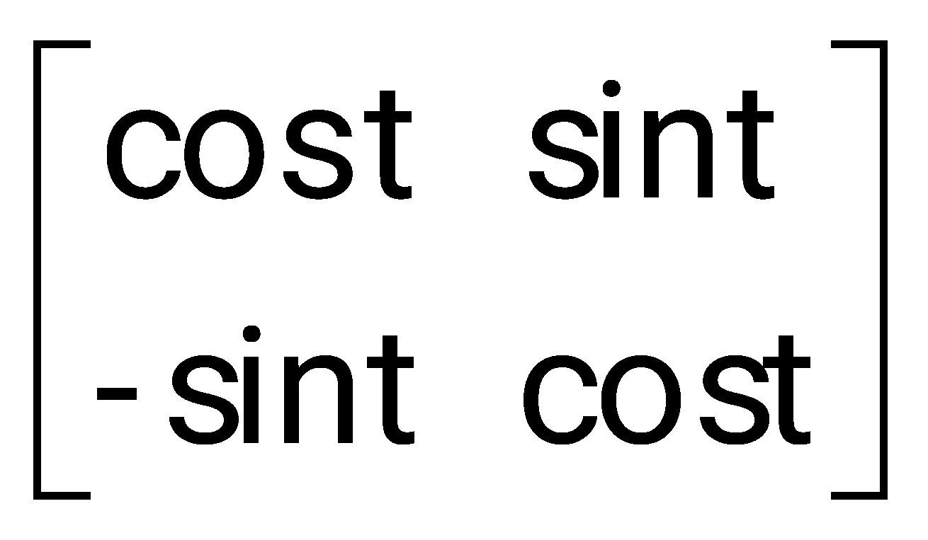
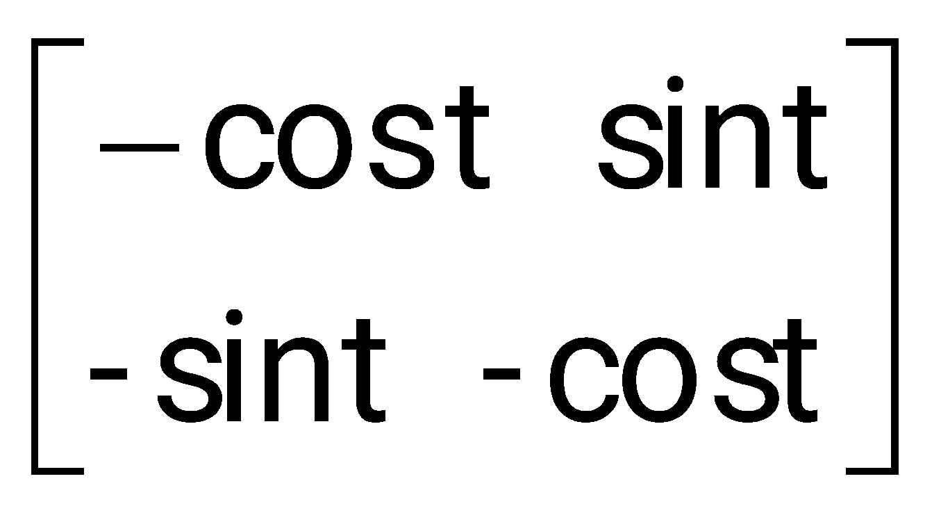
The state-transition matrix of the system is:
Sign in to see the solution
Log in to view the explanation, track your attempts, and keep your progress.
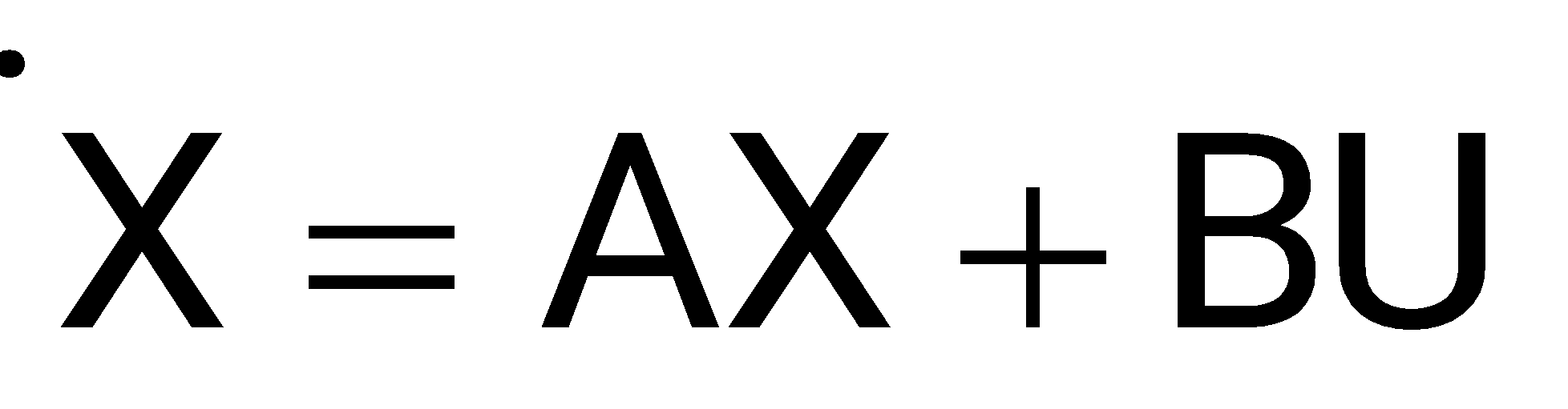
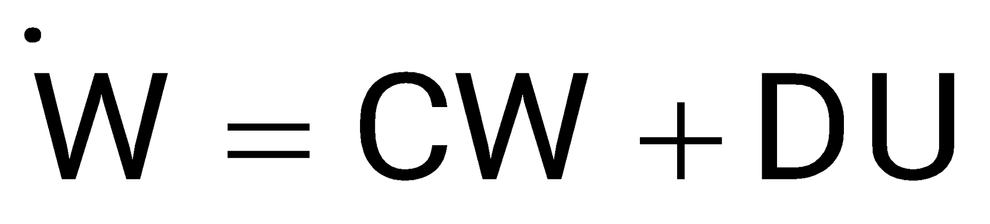
Sign in to UnlockA linear system is equivalently represented by two sets of state equations-
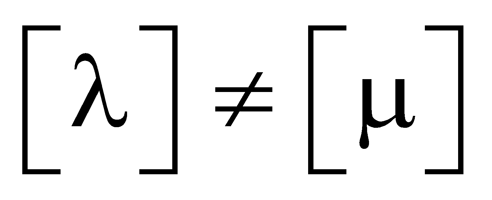
and . The eigen values of the representations are also computed as and . Which one of the following statements is true?
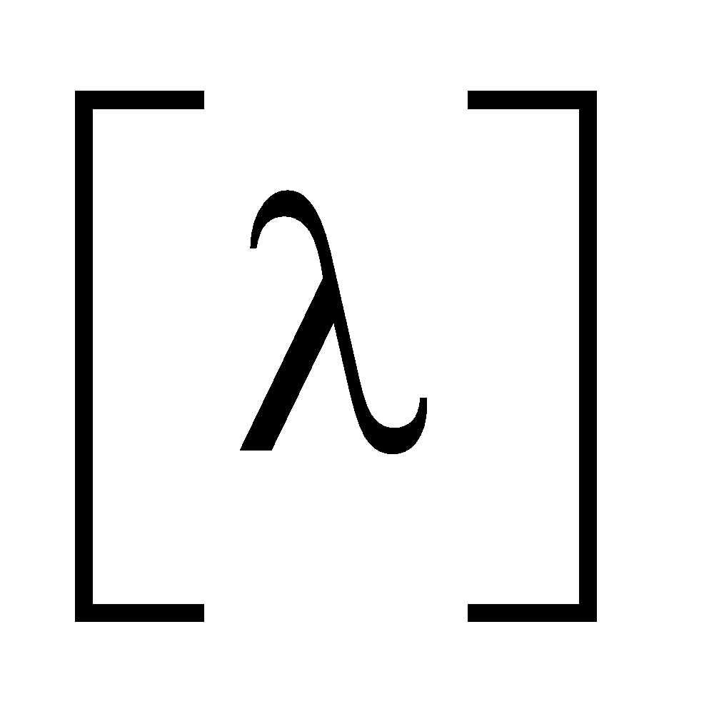
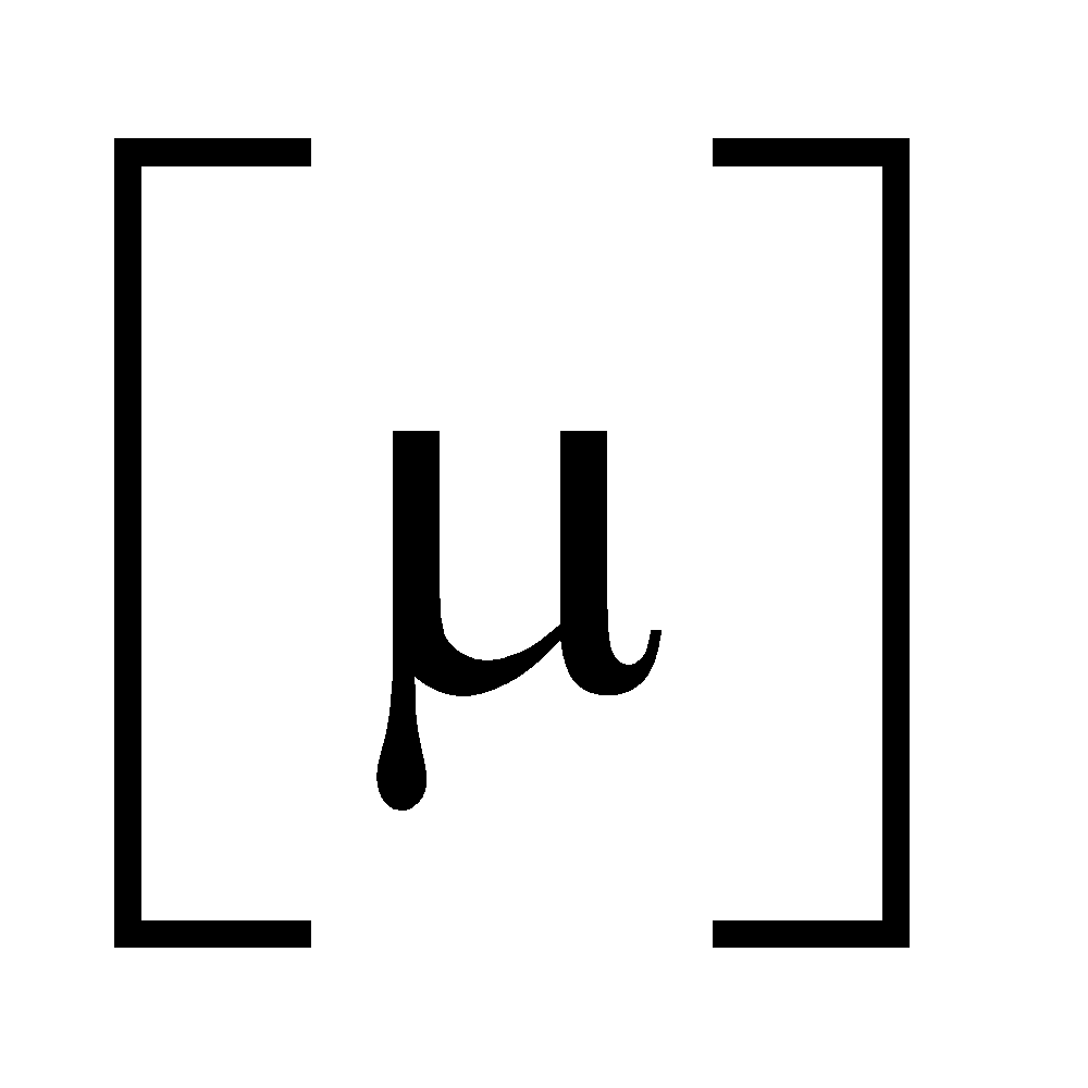
and X = W
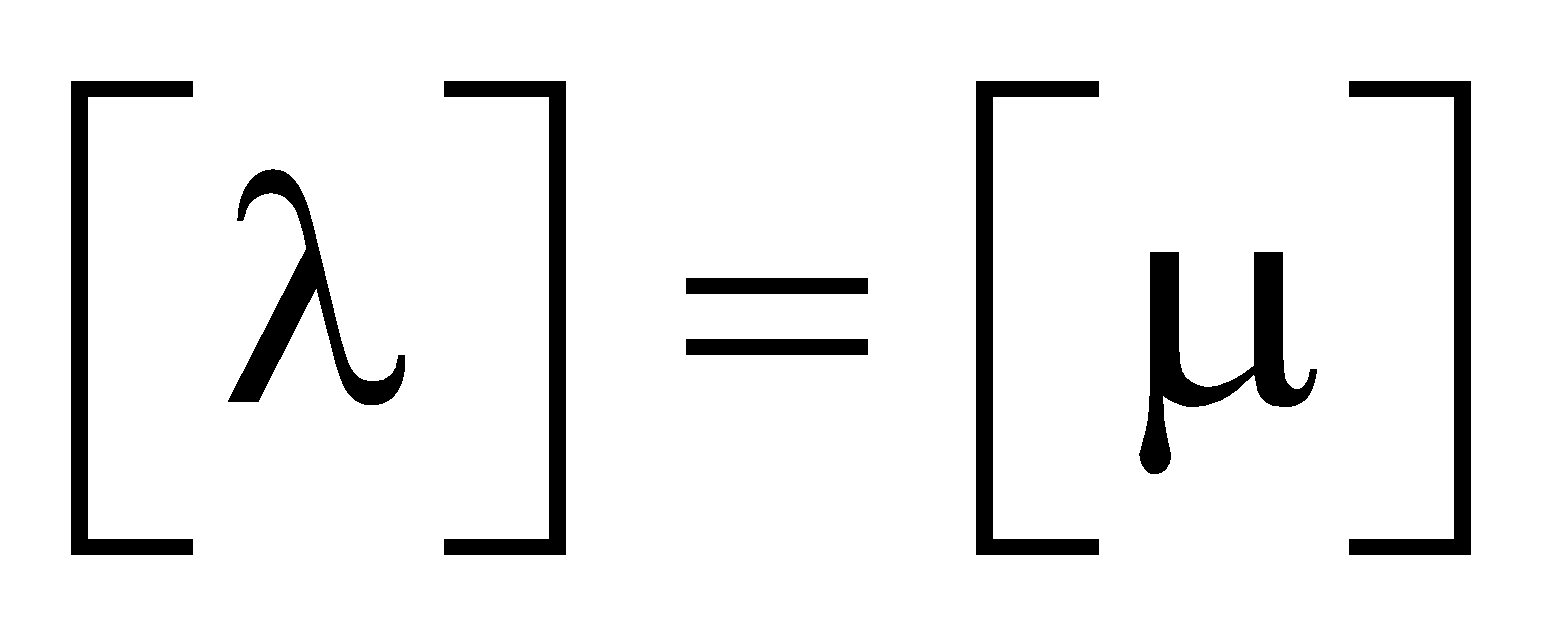
and
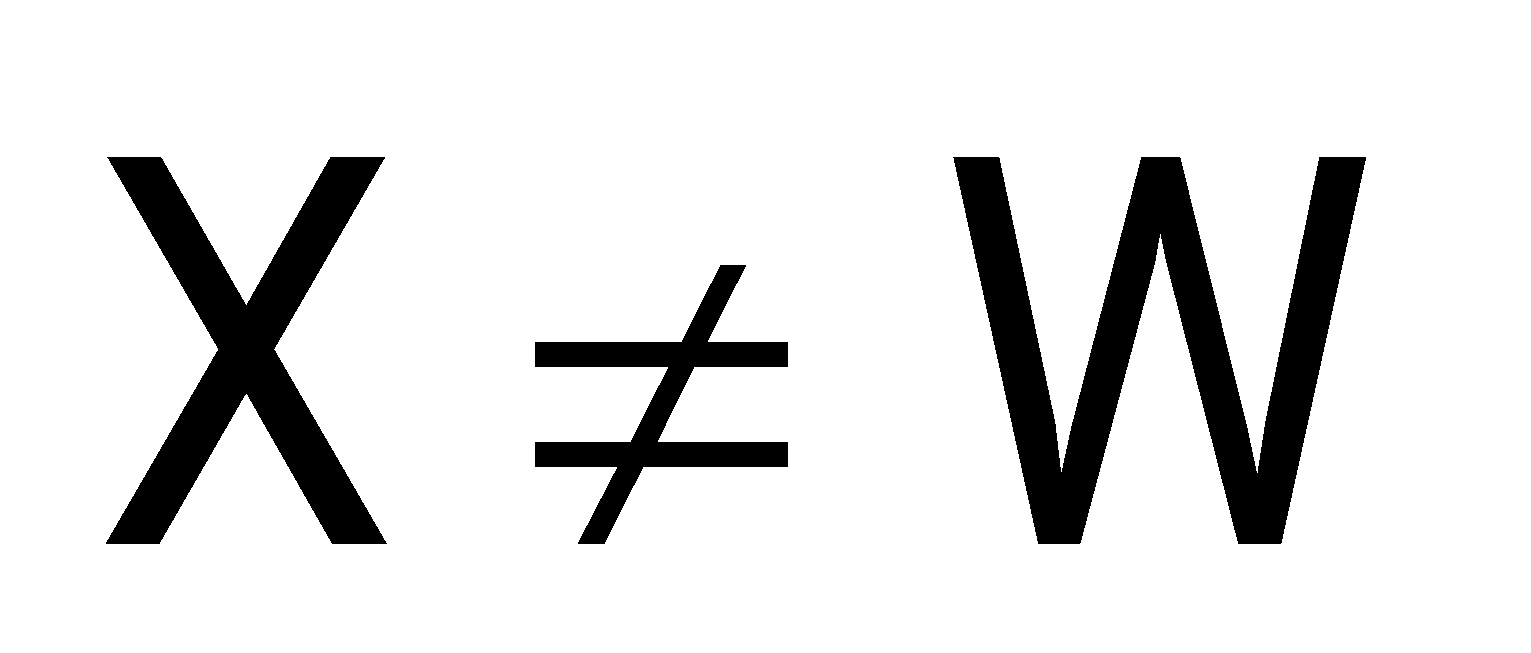
and X = W
and
Sign in to see the solution
Log in to view the explanation, track your attempts, and keep your progress.
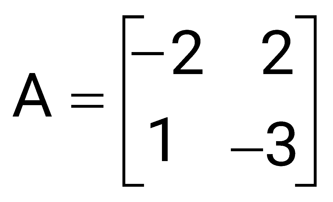
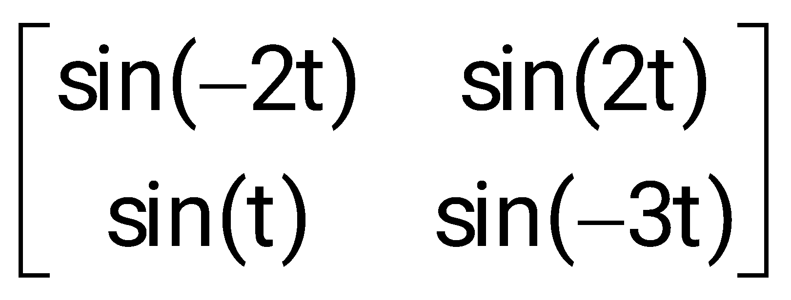
Sign in to UnlockIf then sin At is



Sign in to see the solution
Log in to view the explanation, track your attempts, and keep your progress.
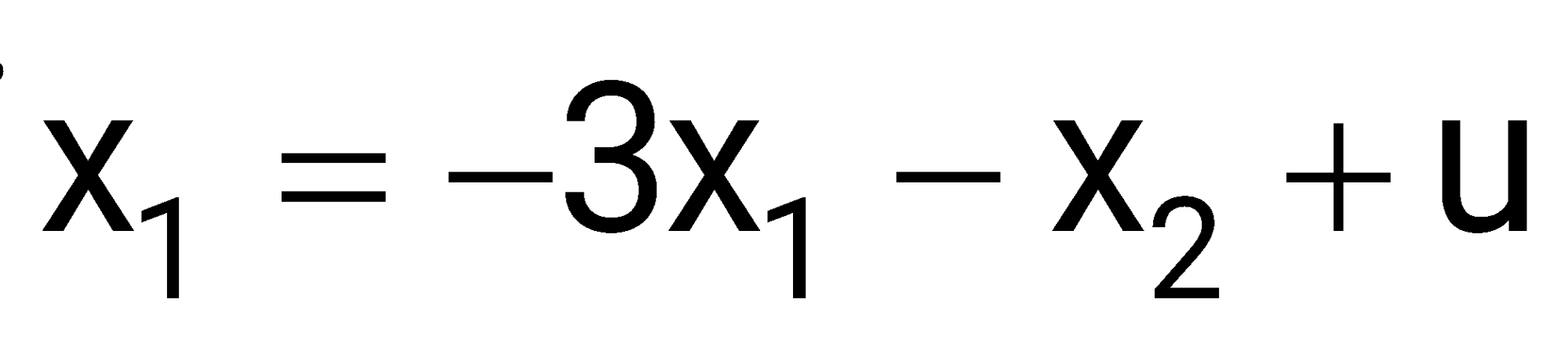
Sign in to UnlockThe state variable equations of a system are:
1.
2.
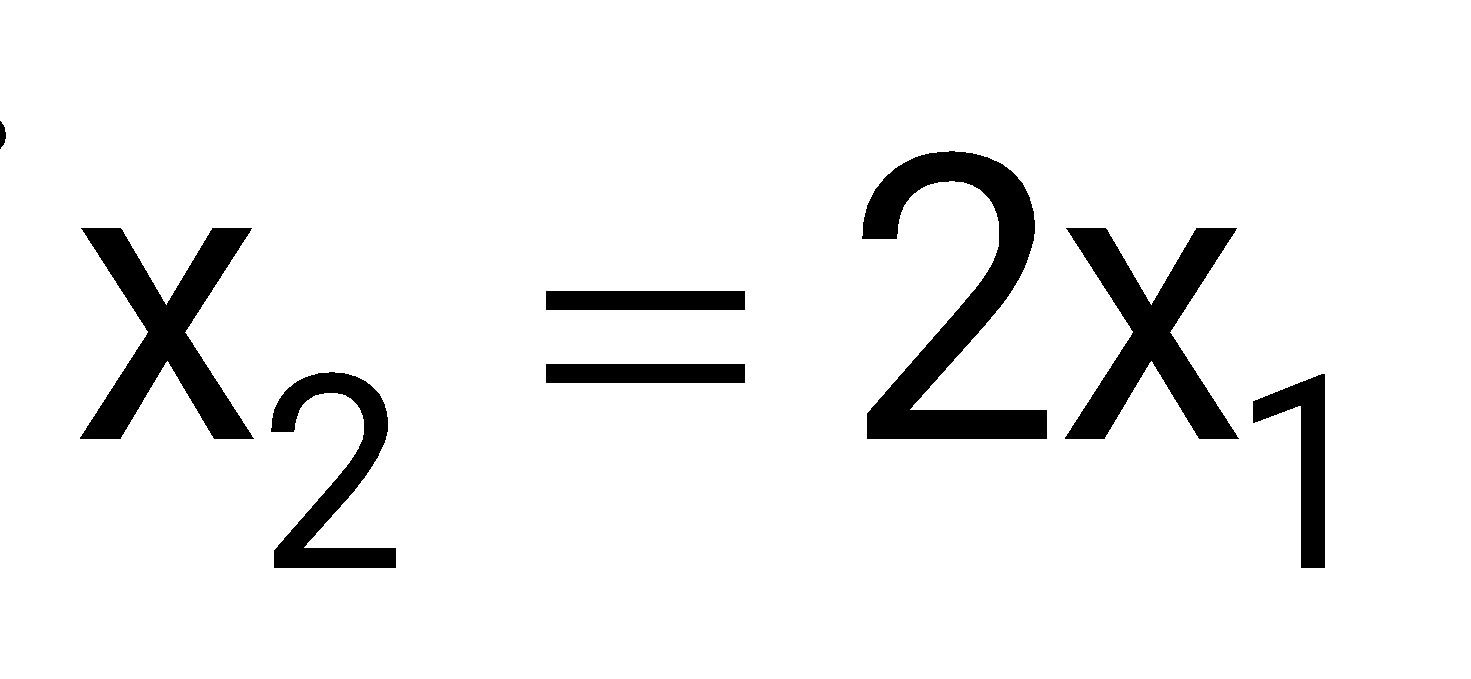
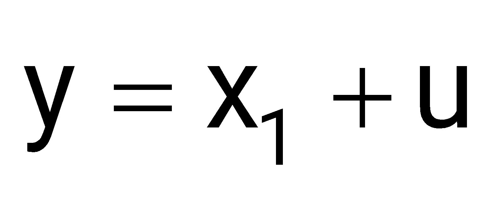
The system is
Sign in to see the solution
Log in to view the explanation, track your attempts, and keep your progress.
Sign in to UnlockGiven the state transition matrix is given by
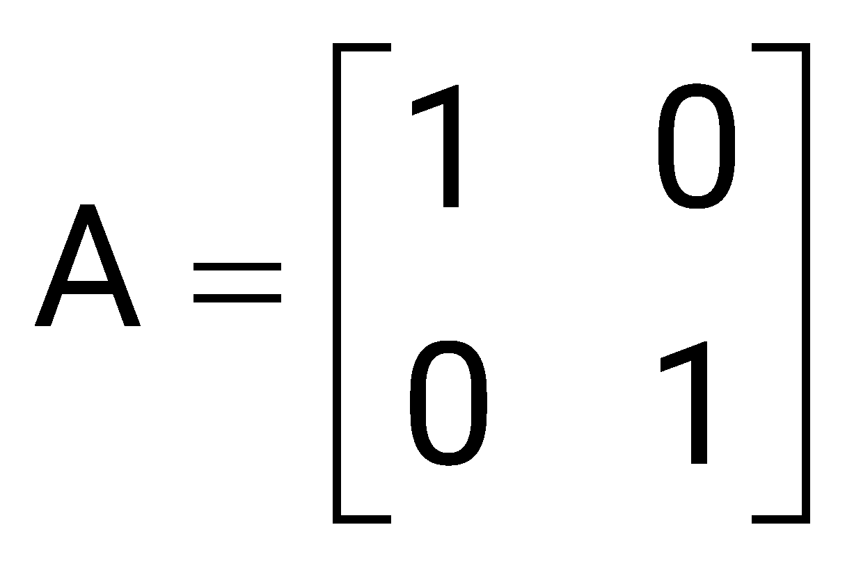
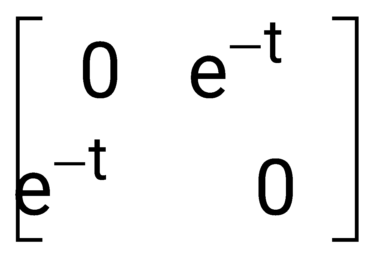
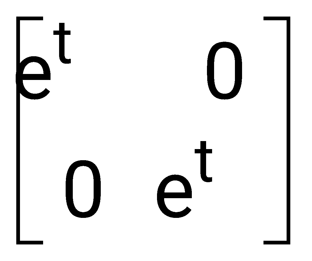
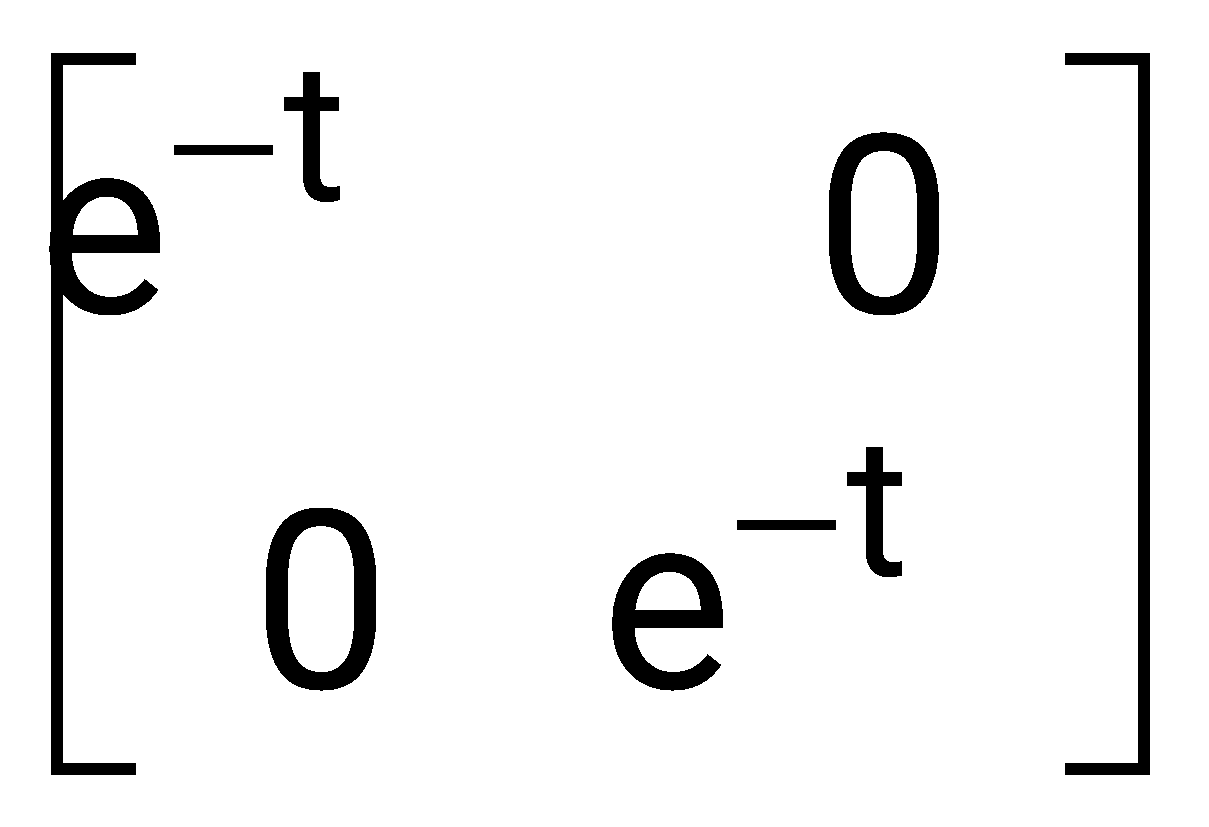
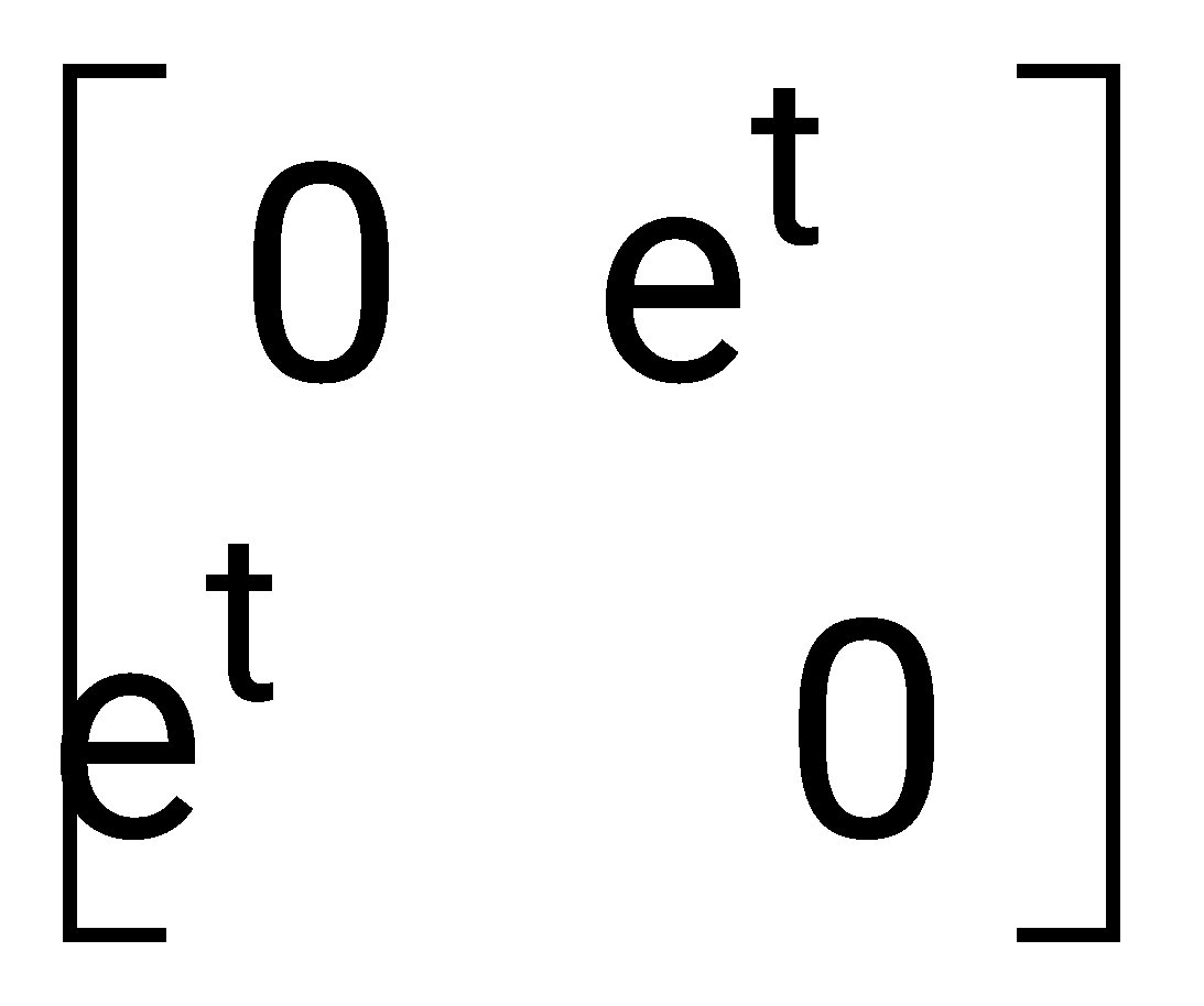
Sign in to see the solution
Log in to view the explanation, track your attempts, and keep your progress.
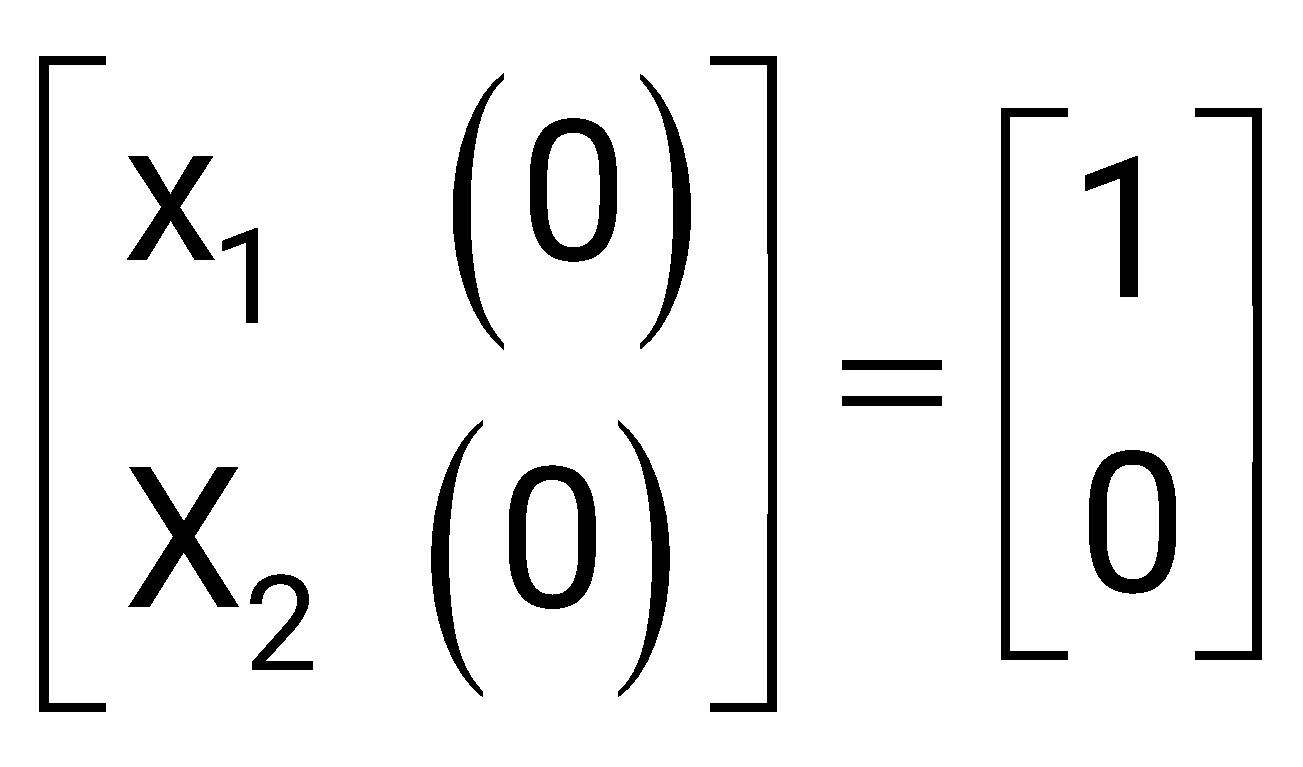
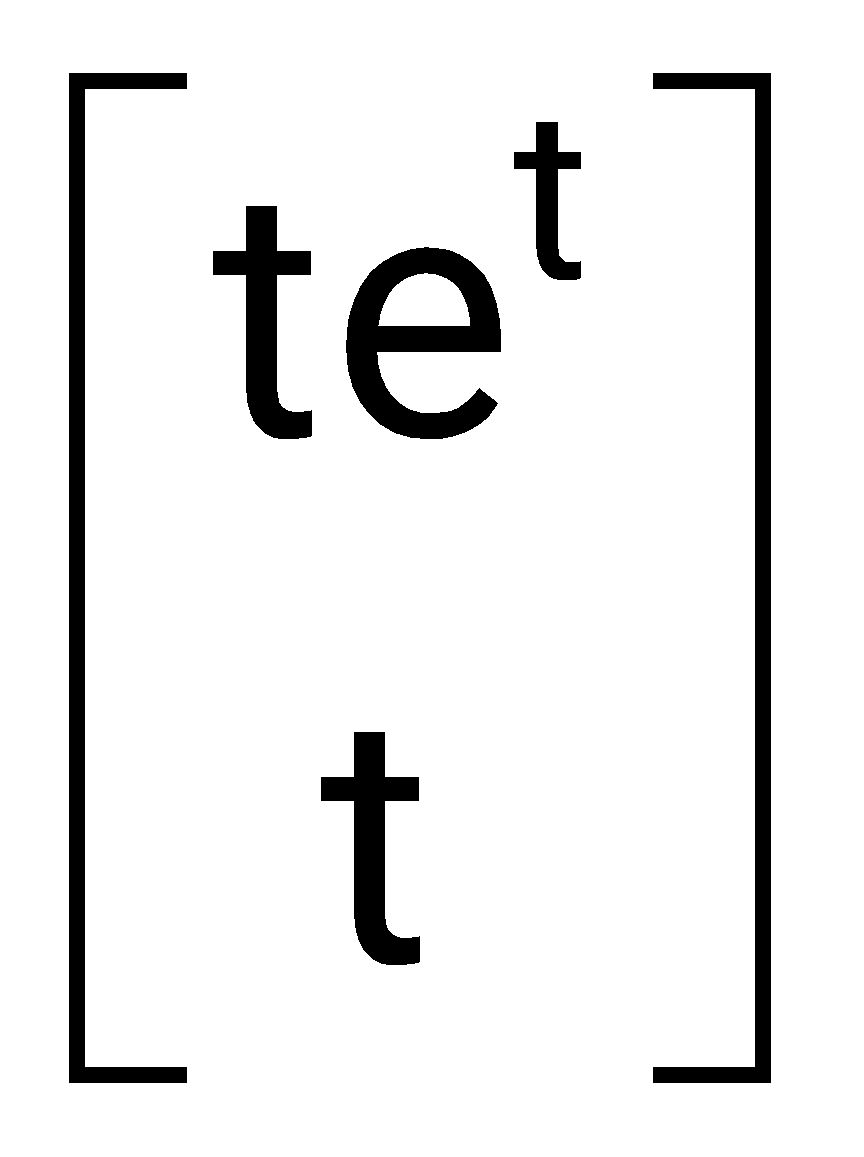
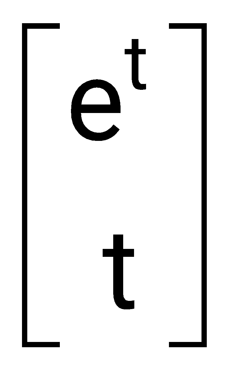
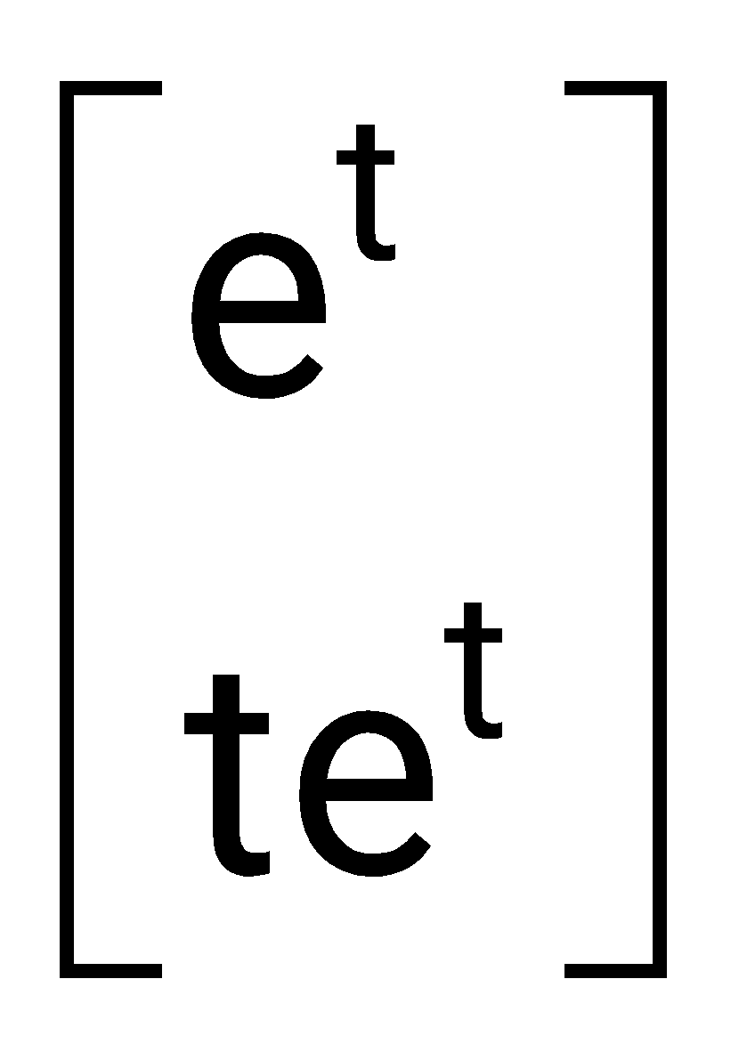
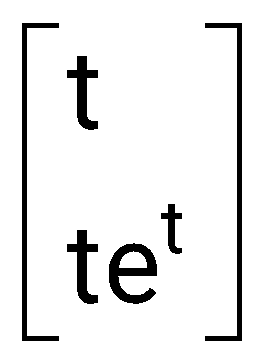
Sign in to UnlockThe zero-input response of a system given by the state-space equation
and is
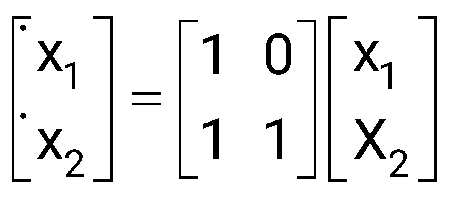
Sign in to see the solution
Log in to view the explanation, track your attempts, and keep your progress.
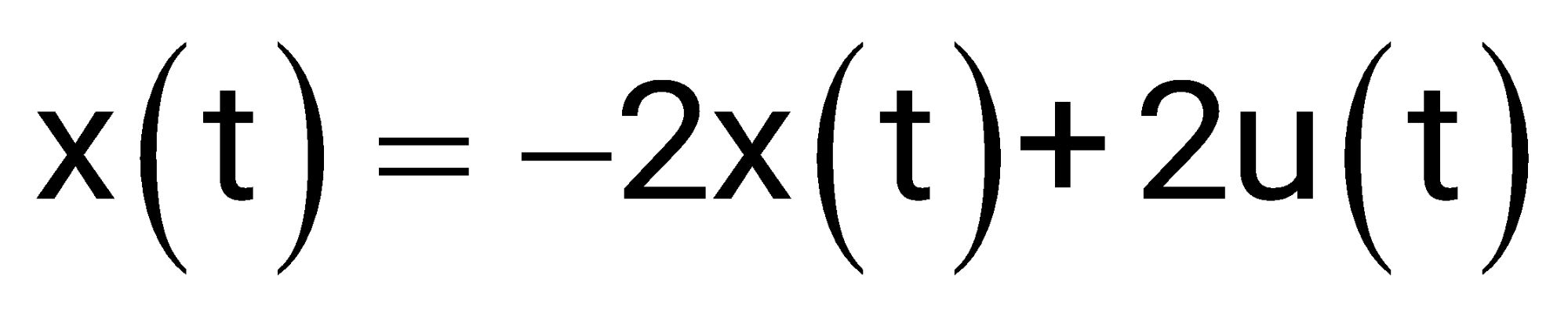
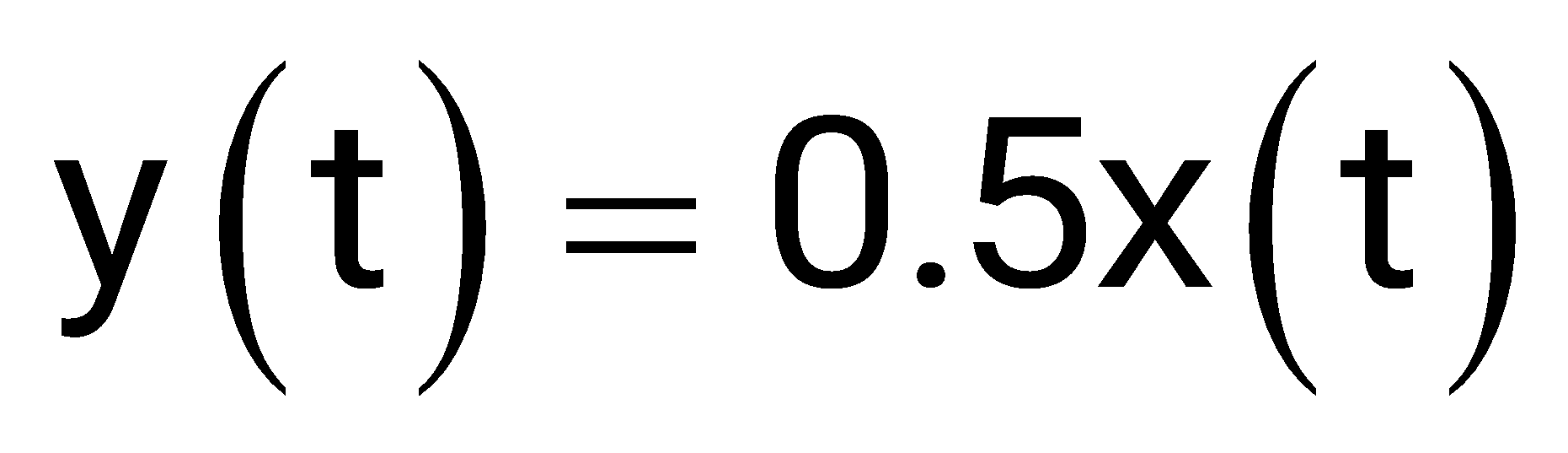
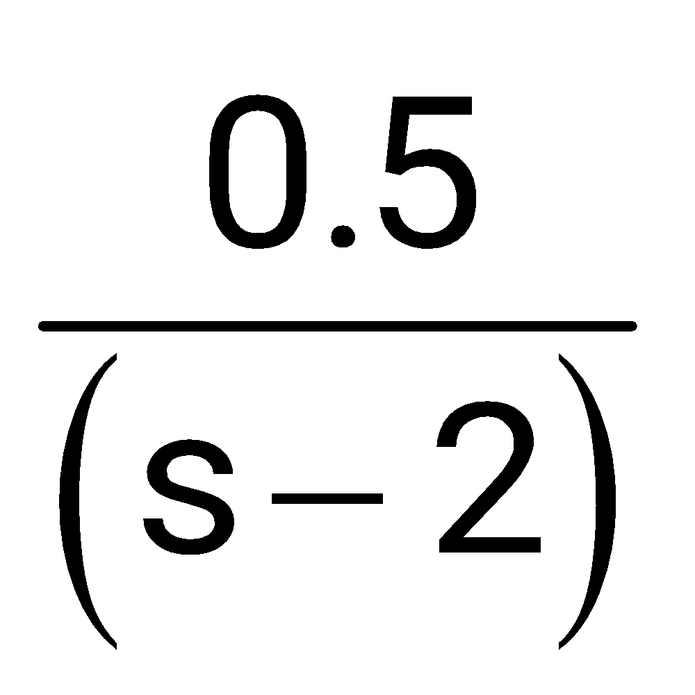
Sign in to UnlockThe transfer function Y(s)/U(s) of a system described by the state equations and is
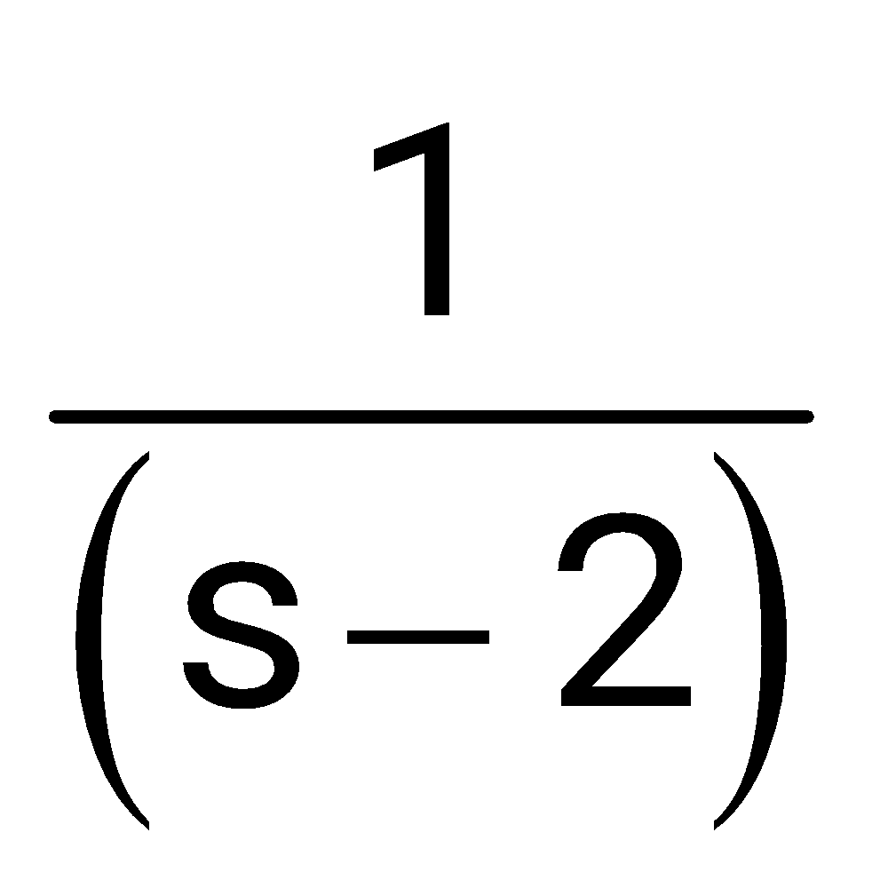
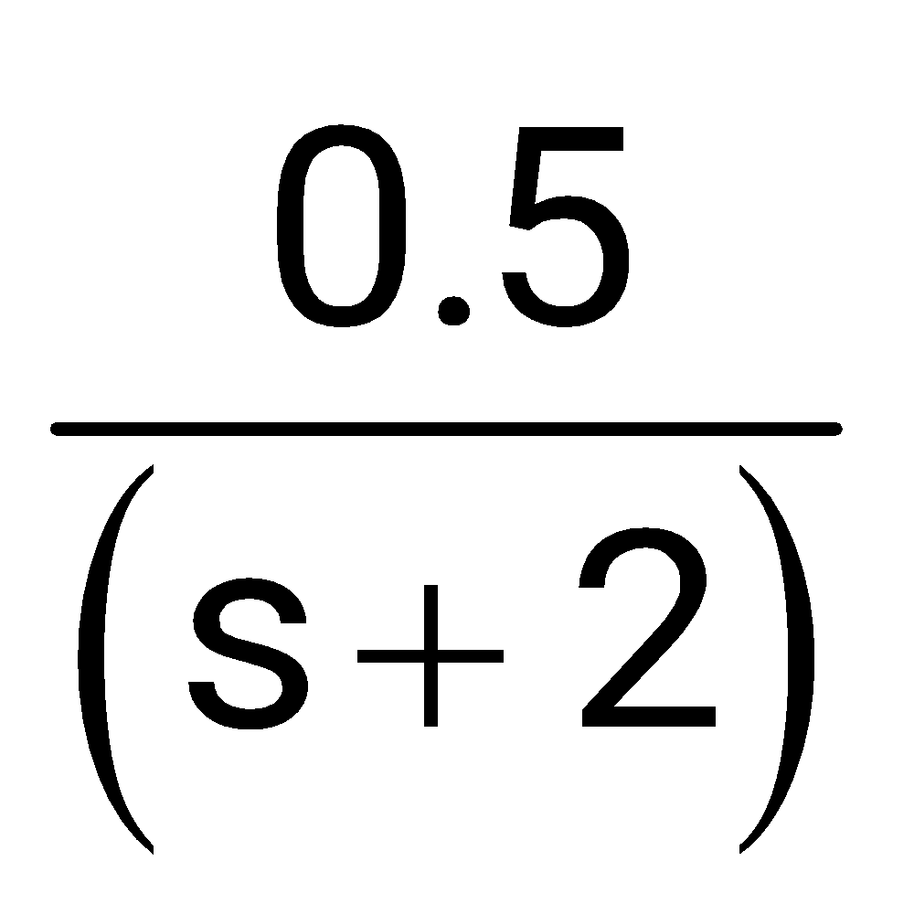
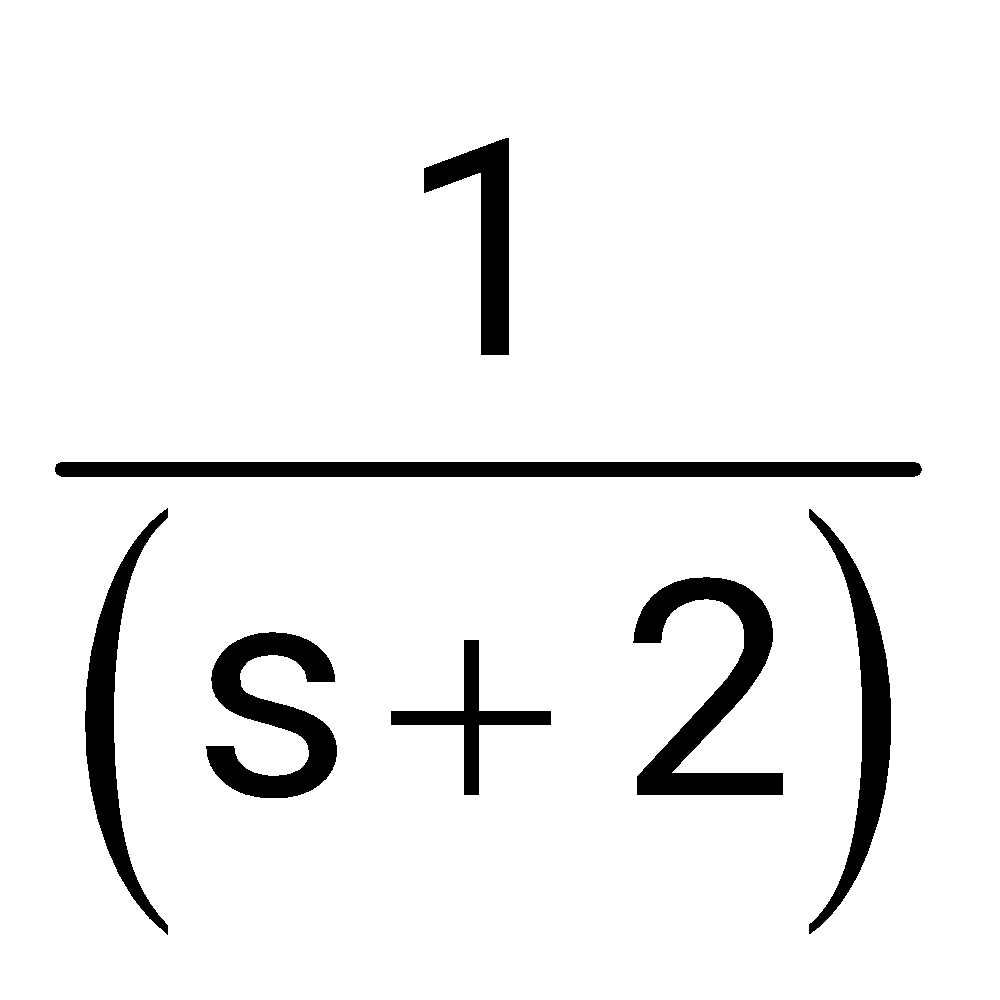
Sign in to see the solution
Log in to view the explanation, track your attempts, and keep your progress.
Sign in to UnlockThe block diagram of a linear time invariant system is given in Figure.
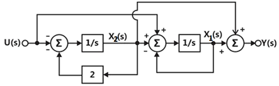
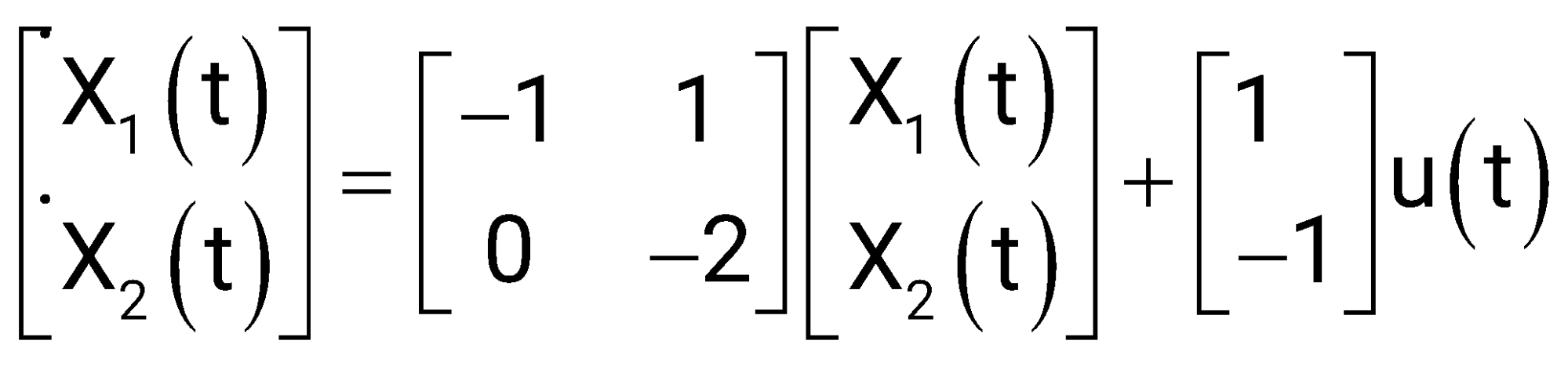
(a) Write down the state variable equations for the system in matrix form assuming the state vector to be .
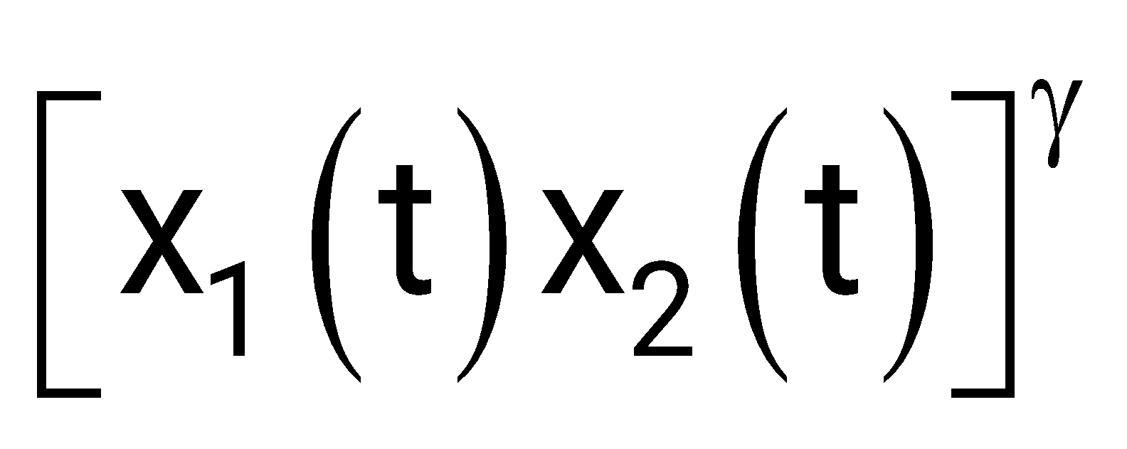
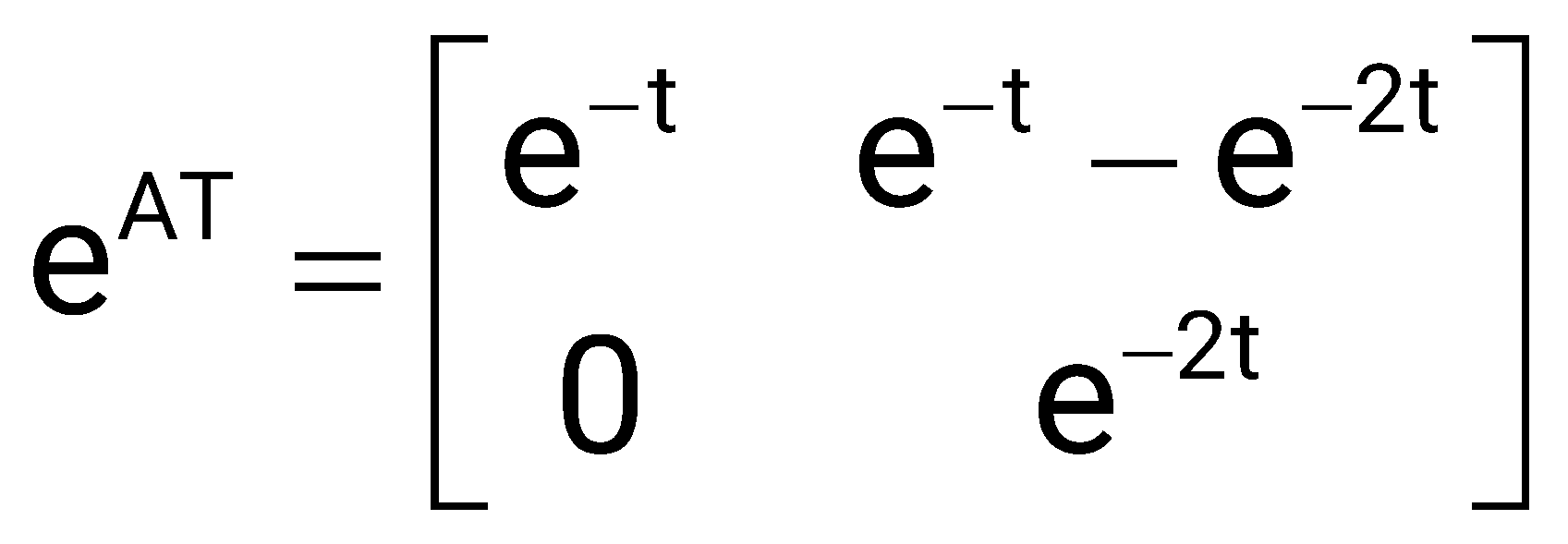
(b) Find out the state transition matrix.
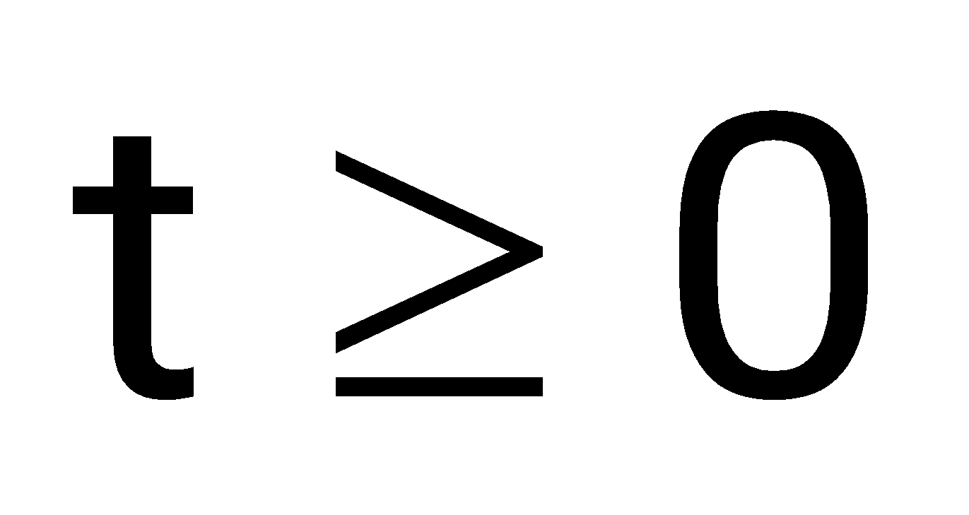
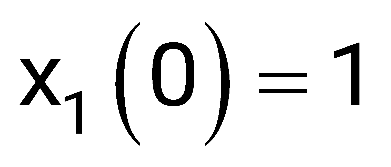
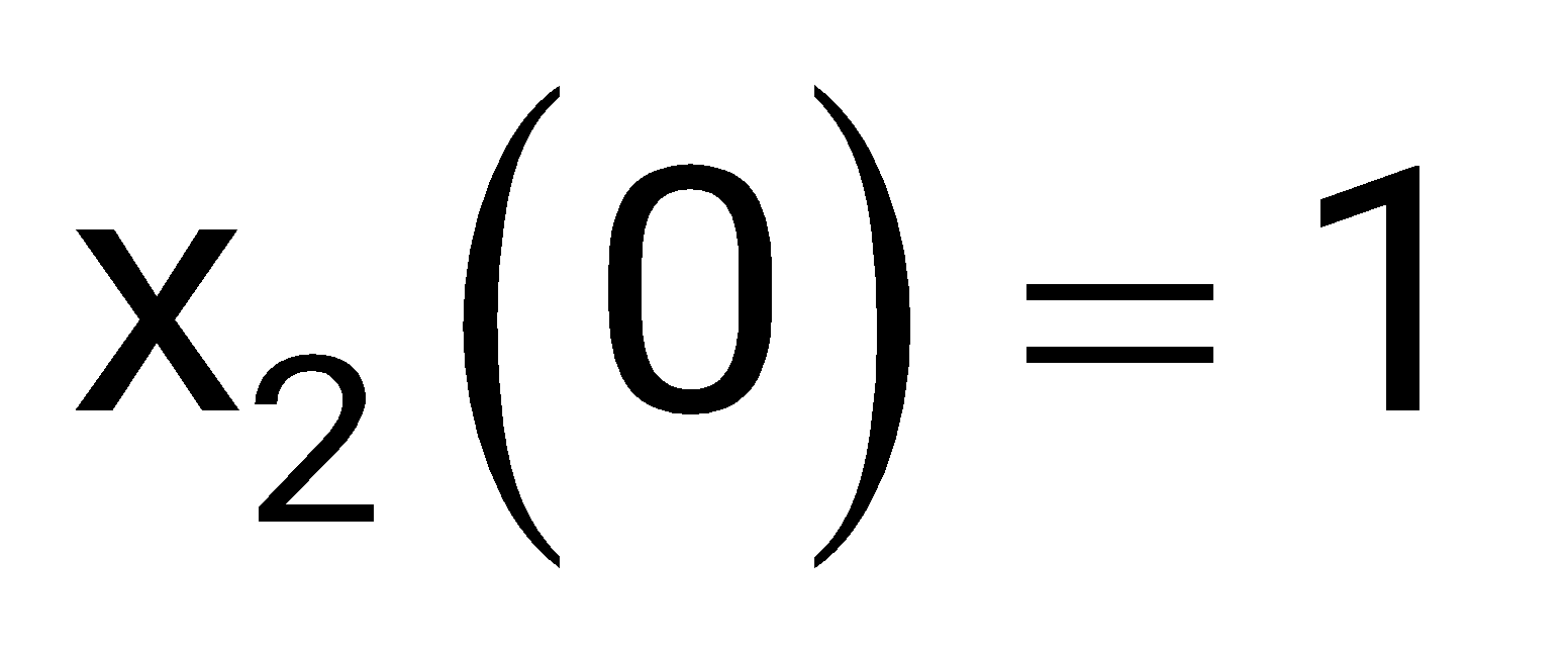
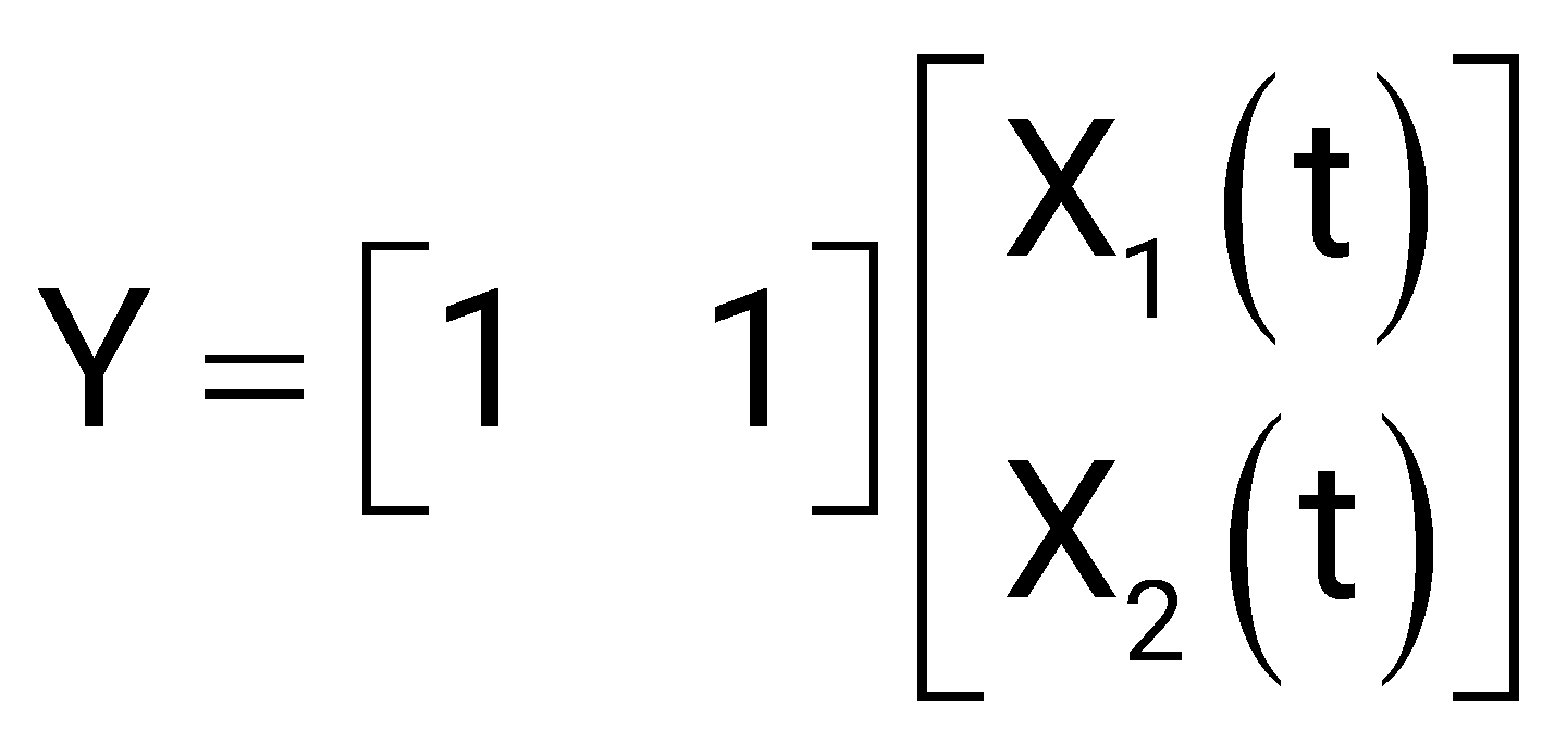
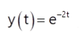
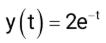
(c) Determine y(t), , when the initial values of the state at time t = 0 are , and .
Sign in to see the solution
Log in to view the explanation, track your attempts, and keep your progress.
Sign in to UnlockA certain linear, time-invariant system has the state and output representation shown below:
And
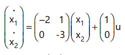
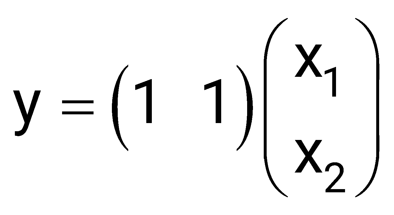
(a) Find the eigen values (natural frequencies) of the system.
(b) If and find , and y(t), for .
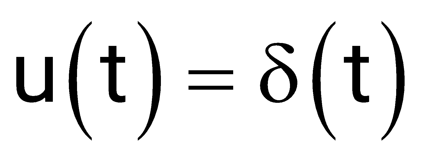
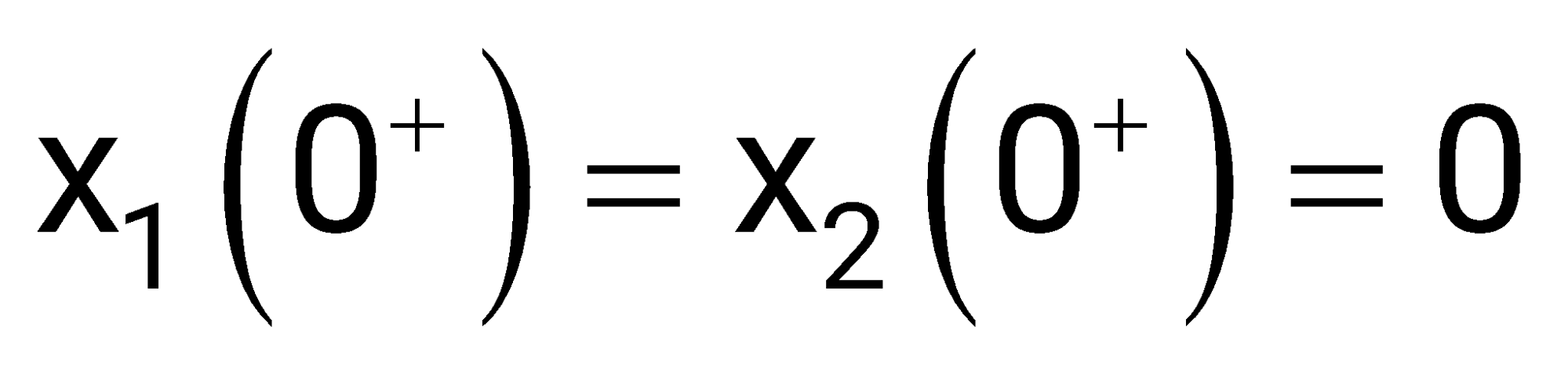
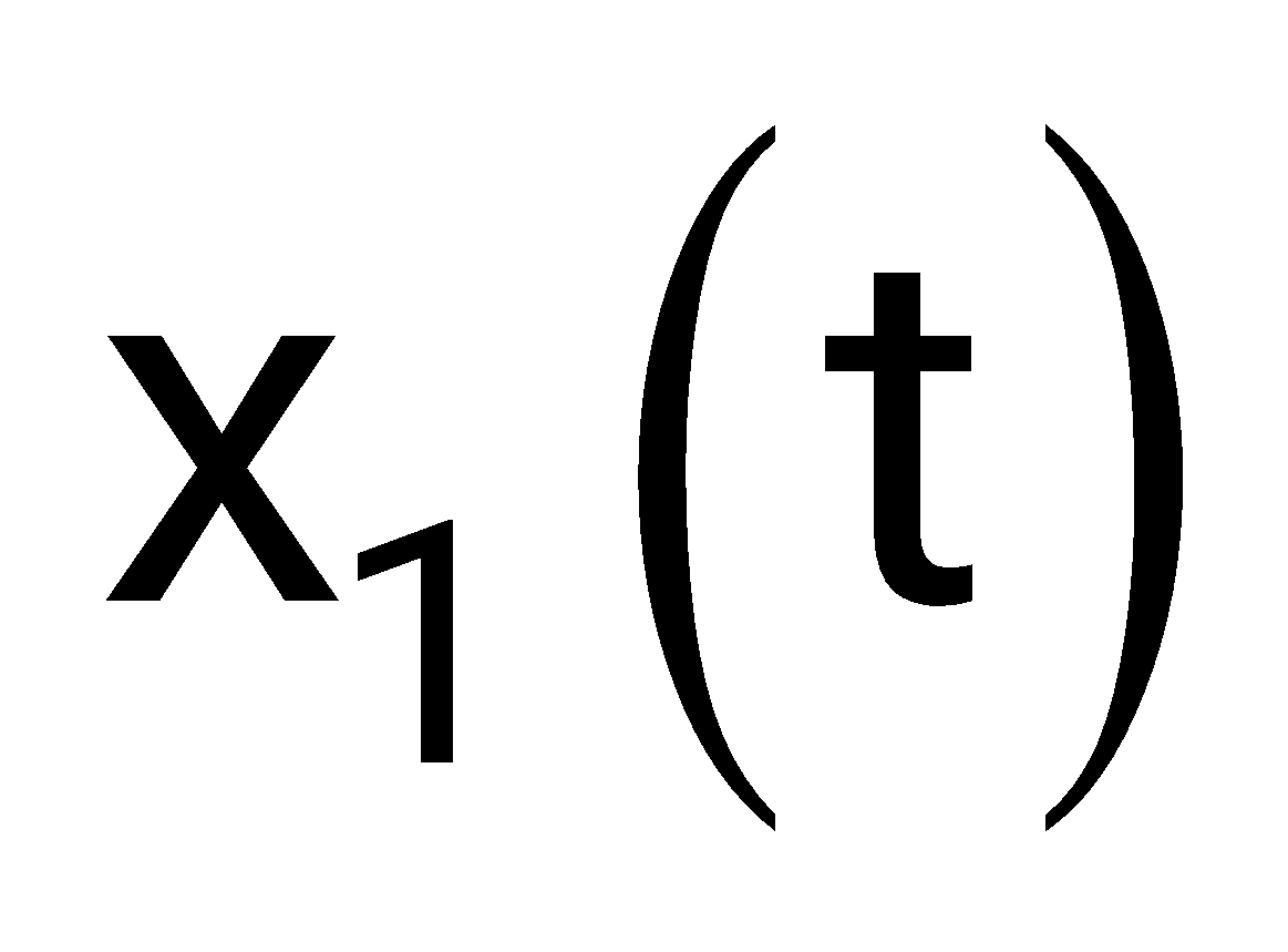
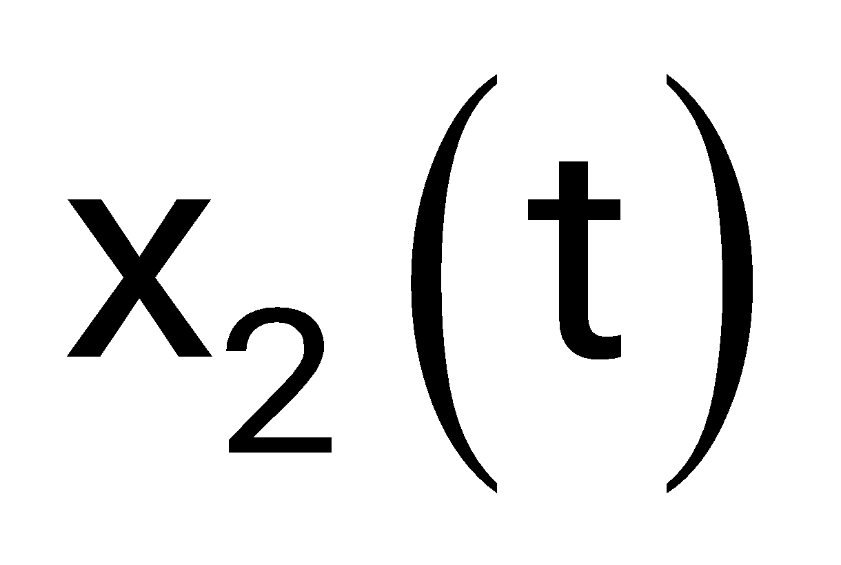
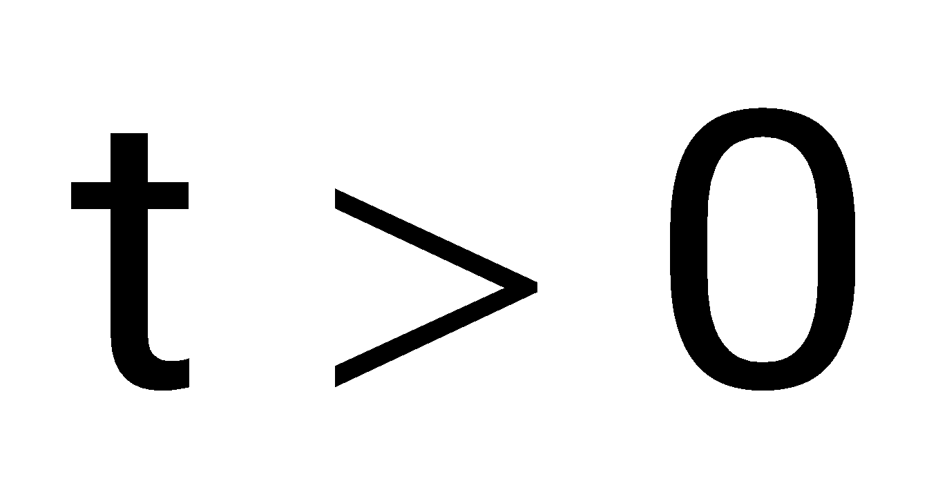
(c) When the input is zero, choose initial conditions
and such that for
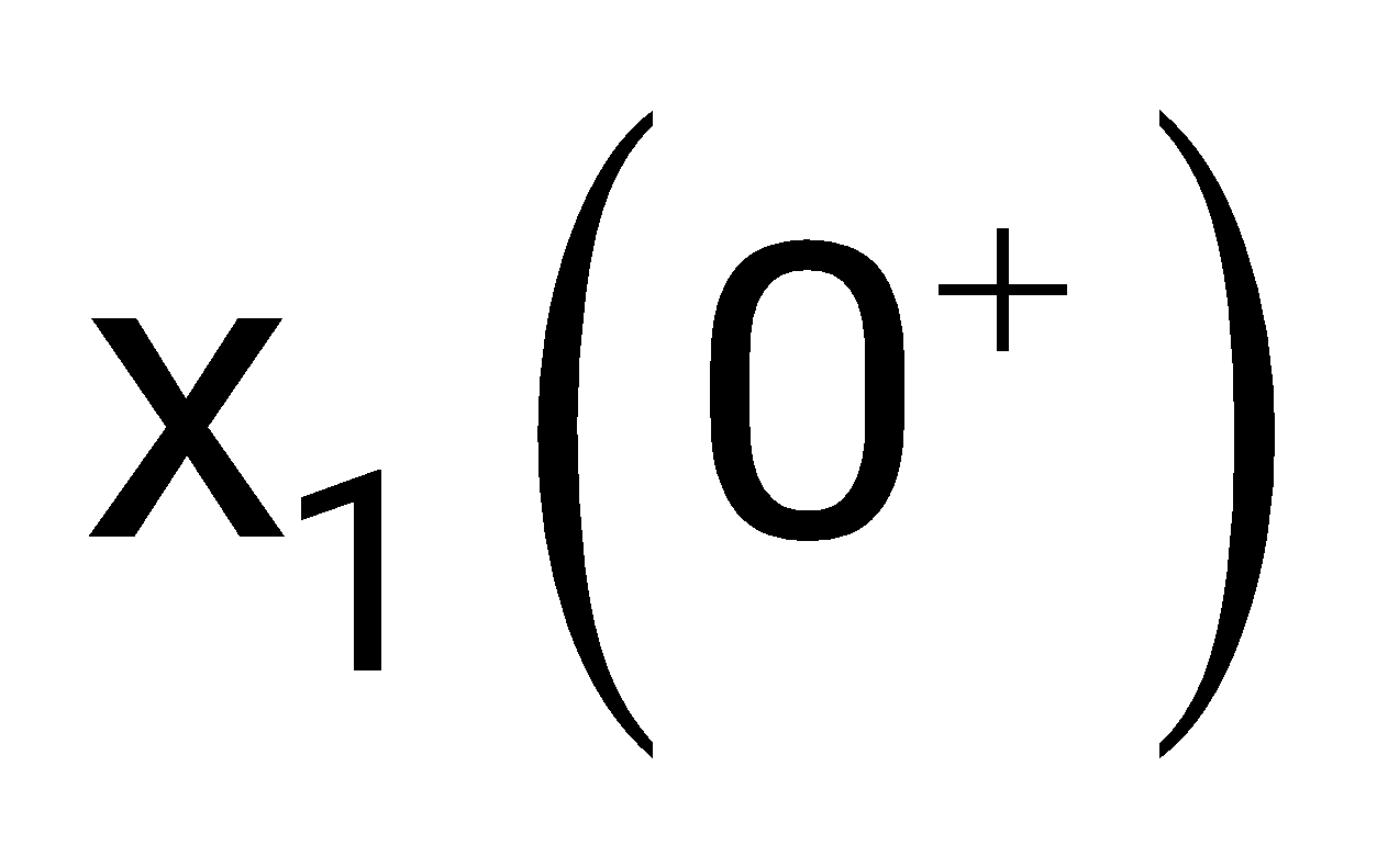
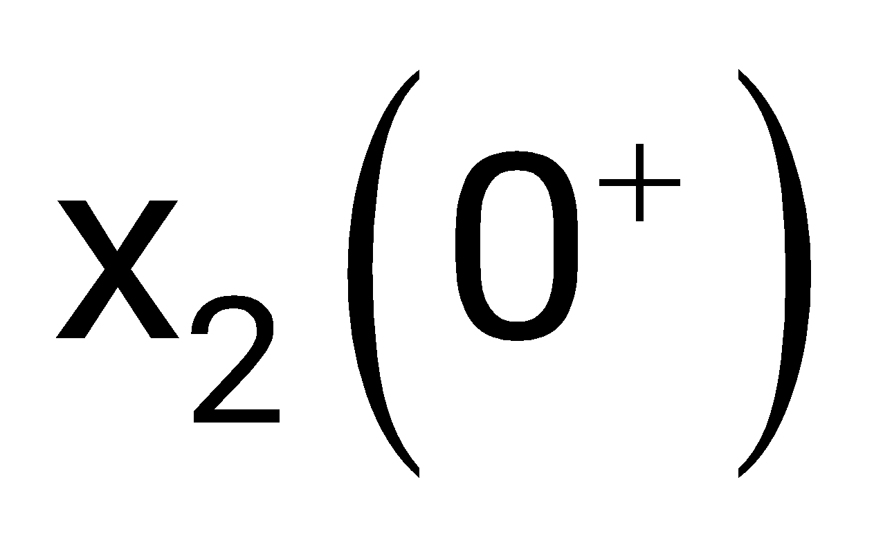
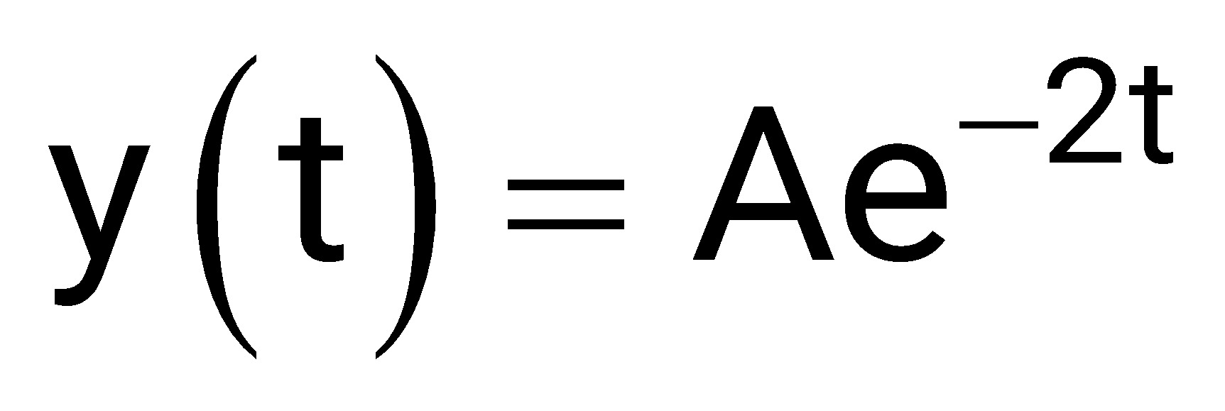
Eigen values


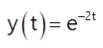
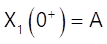
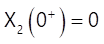
None
Sign in to see the solution
Log in to view the explanation, track your attempts, and keep your progress.
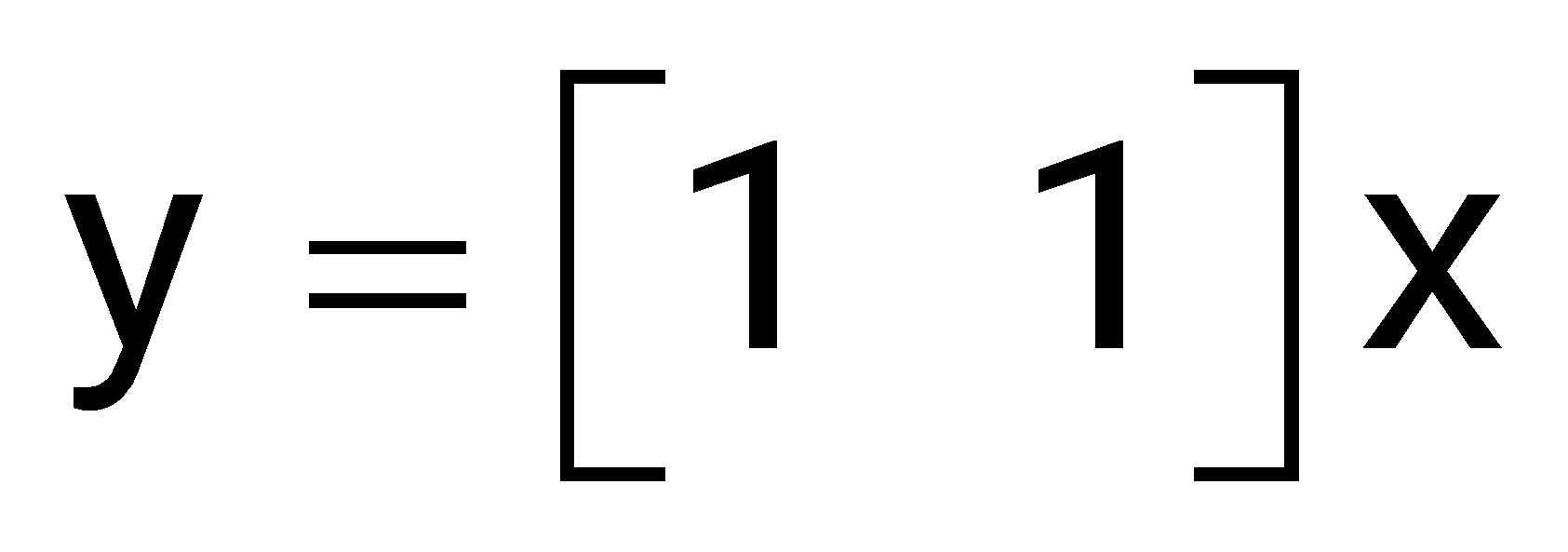
Sign in to UnlockThe system mode described by the state equations
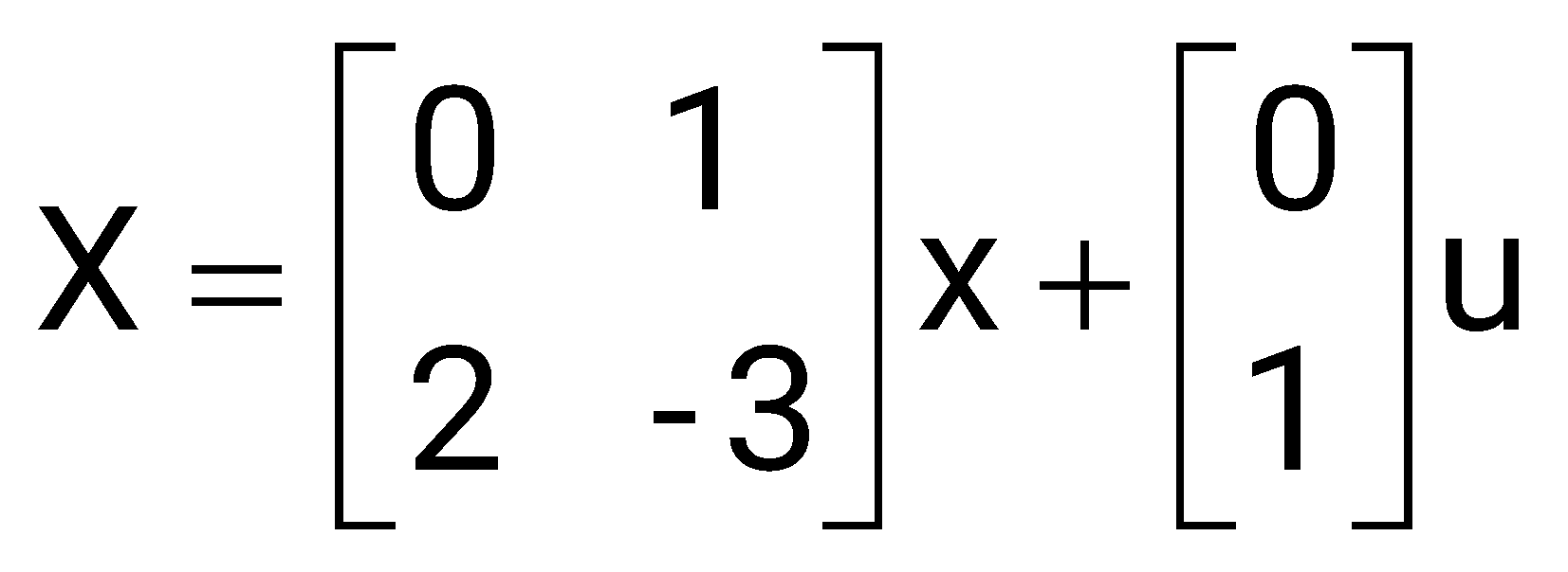
is:
Sign in to see the solution
Log in to view the explanation, track your attempts, and keep your progress.
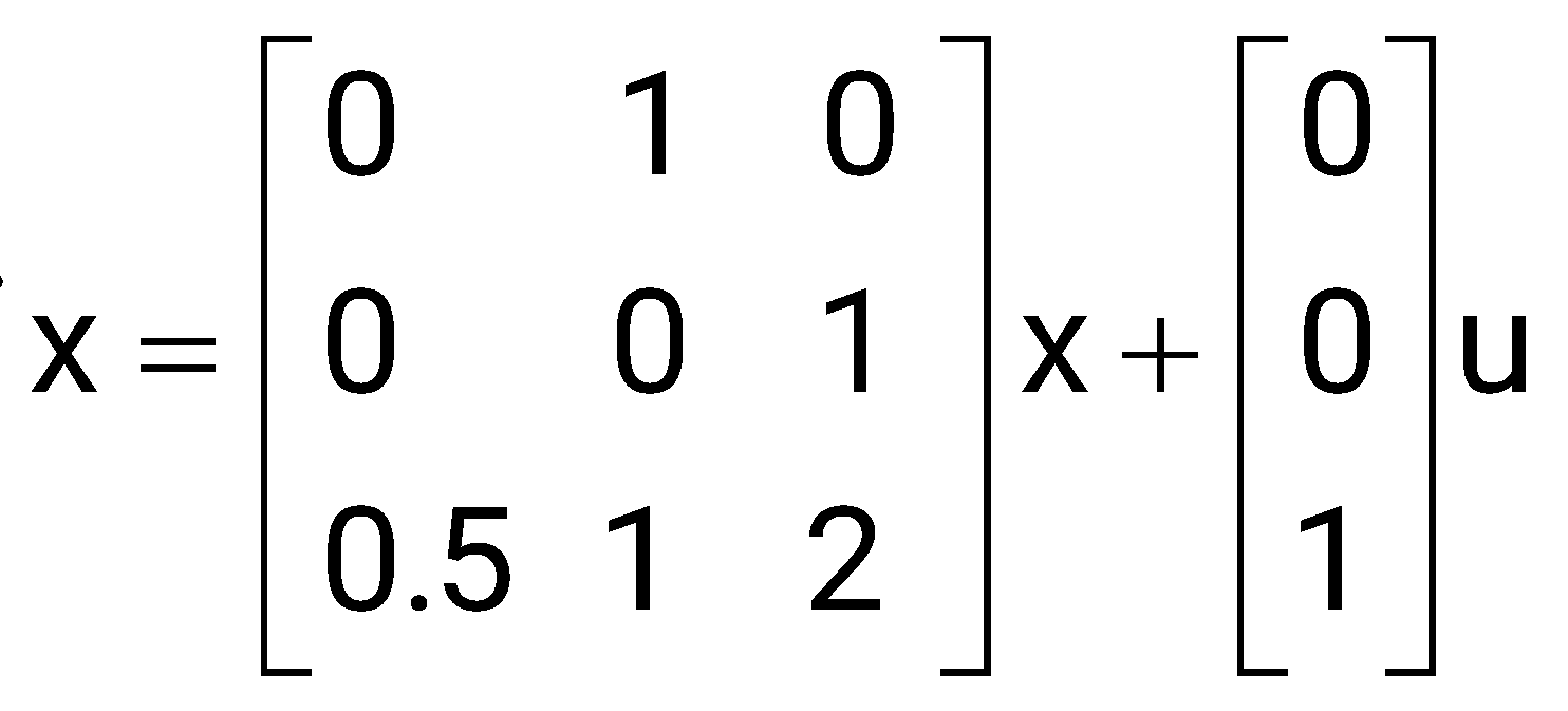
Sign in to UnlockFor the system described by the state equation. If the control signal u is given by, then the Eigen values of the closed-loop system will be

Sign in to see the solution
Log in to view the explanation, track your attempts, and keep your progress.
Sign in to UnlockA certain linear time invariant system has the sate and the output equations given below
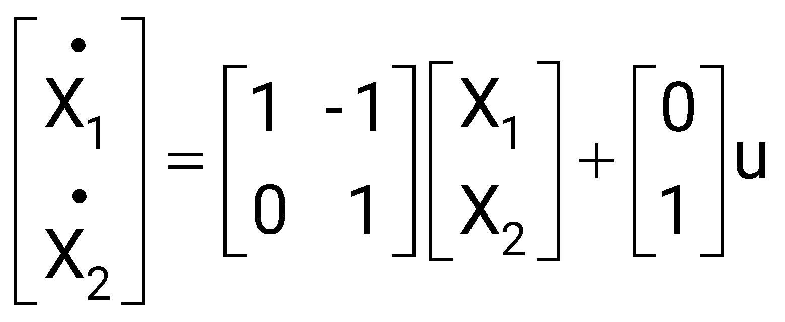
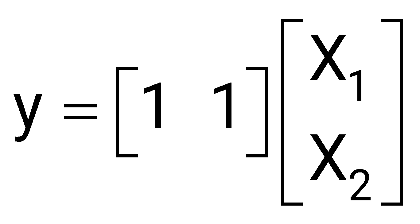
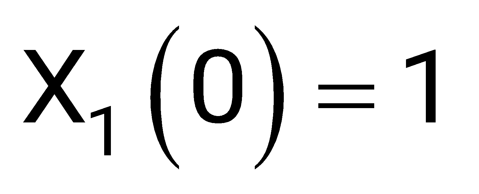
If , , , then is
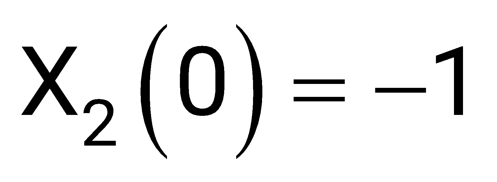
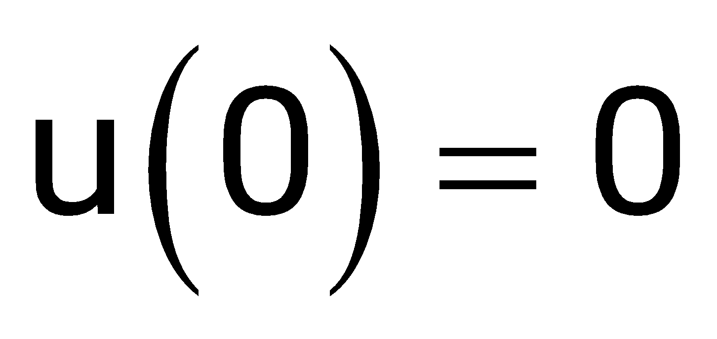
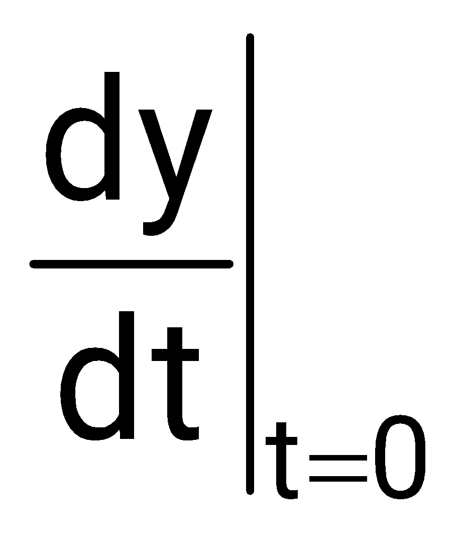
Sign in to see the solution
Log in to view the explanation, track your attempts, and keep your progress.
Sign in to Unlockcan be expanded as
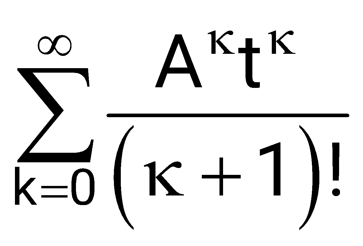
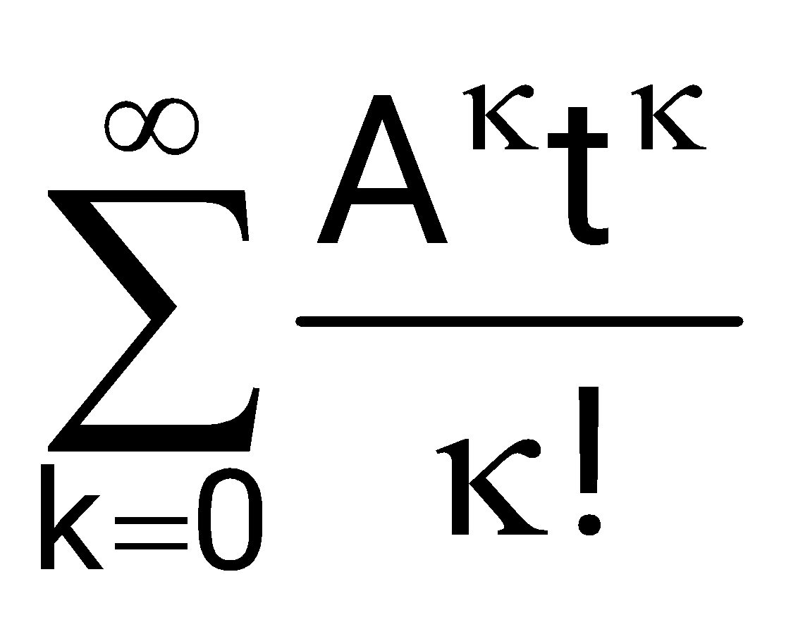
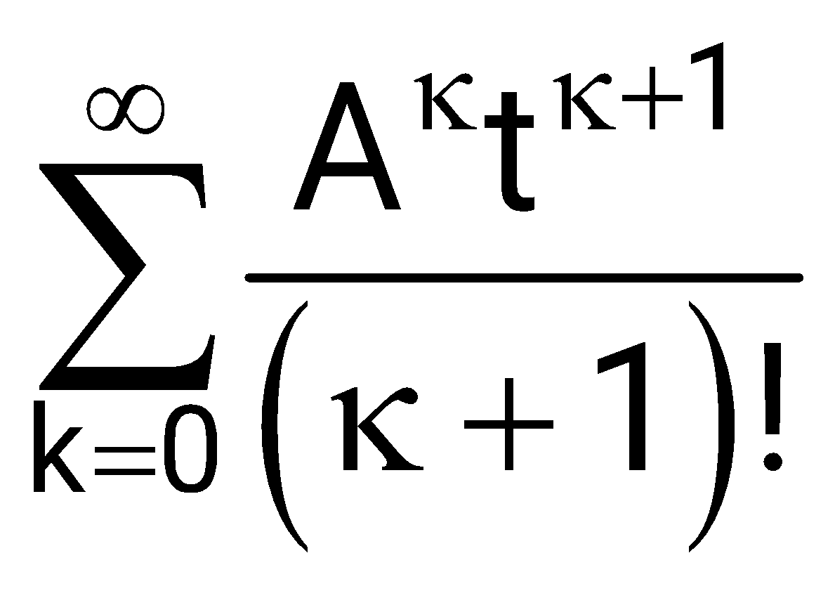
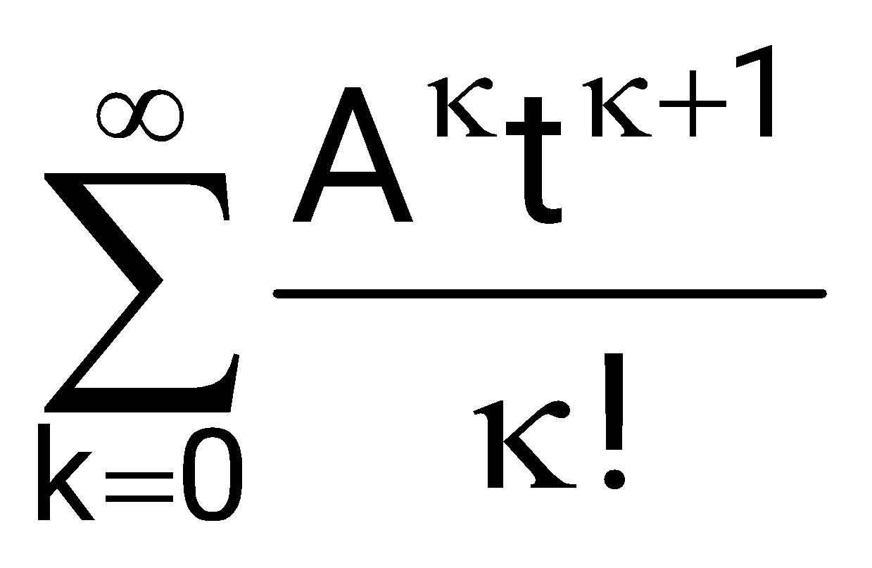
Sign in to see the solution
Log in to view the explanation, track your attempts, and keep your progress.
Sign in to UnlockThe solution of , is
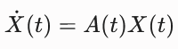
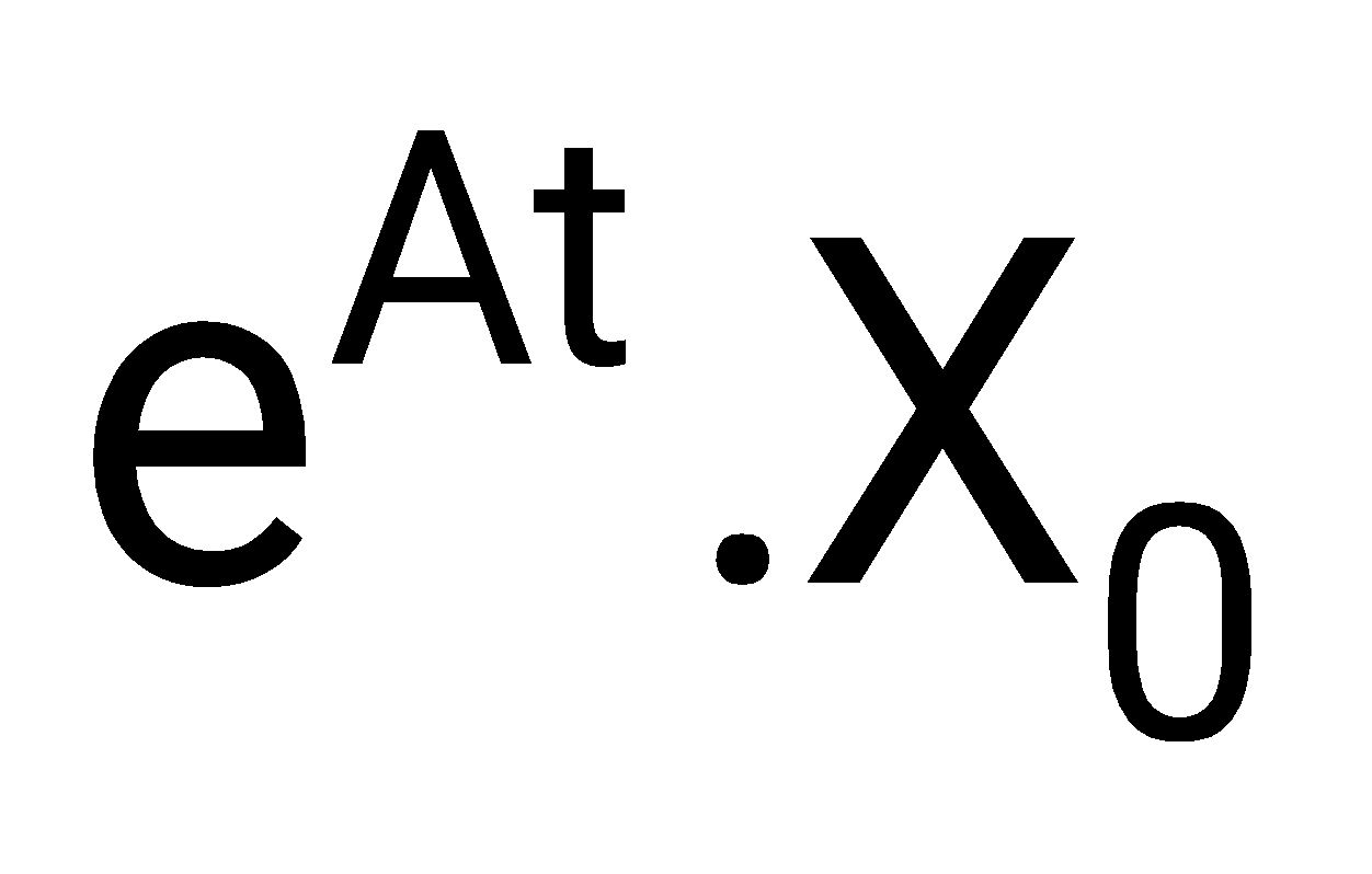
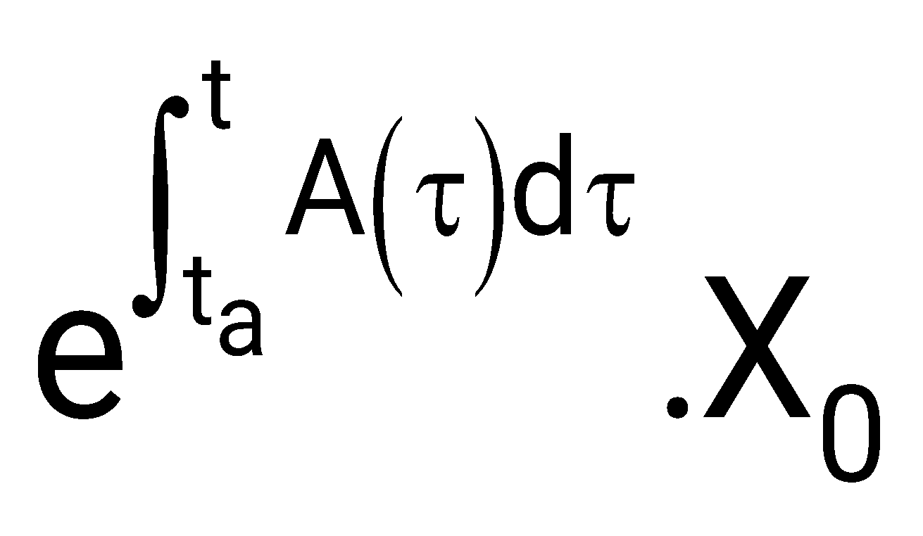
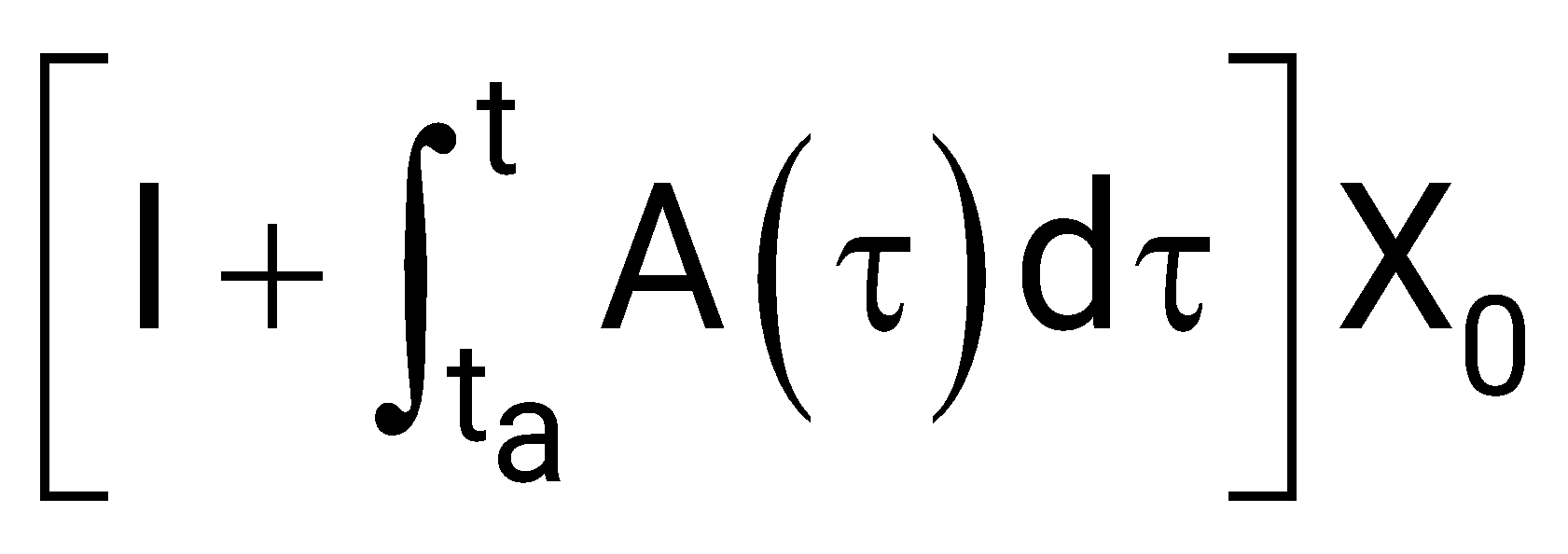
none of these
Sign in to see the solution
Log in to view the explanation, track your attempts, and keep your progress.
Sign in to UnlockA linear time invariant system is described by the state variable model
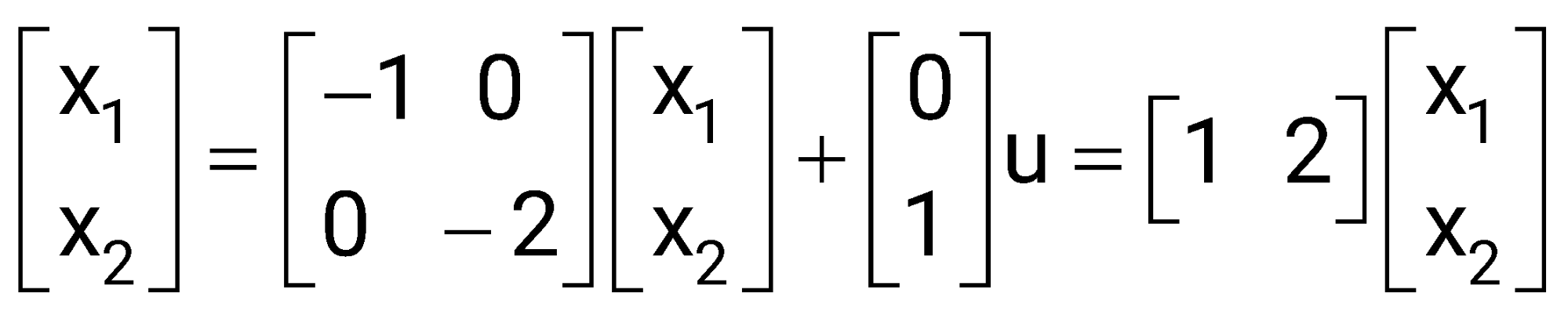
Sign in to see the solution
Log in to view the explanation, track your attempts, and keep your progress.
Sign in to UnlockA linear second order single input continuous time system is described by the following set of differential equations


Where and are the state variables and u(t) is the control variable. The system is:
Sign in to see the solution
Log in to view the explanation, track your attempts, and keep your progress.
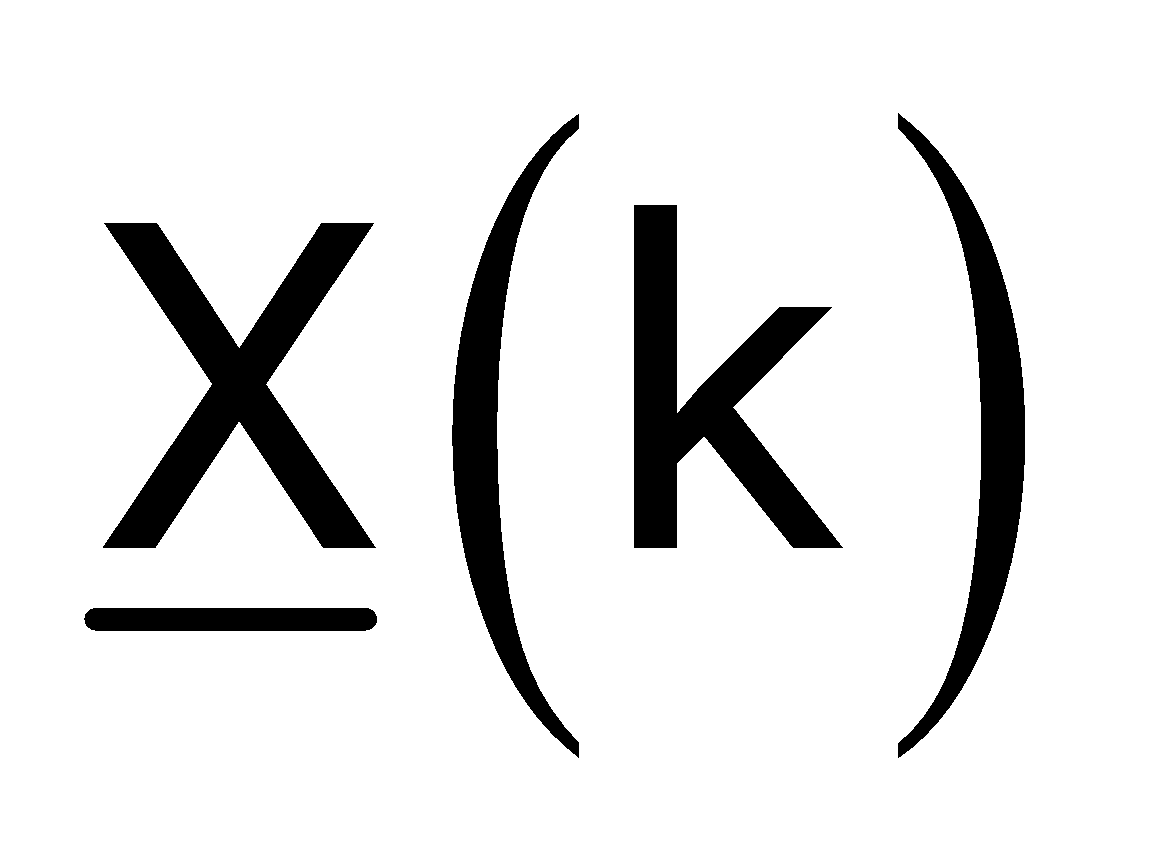
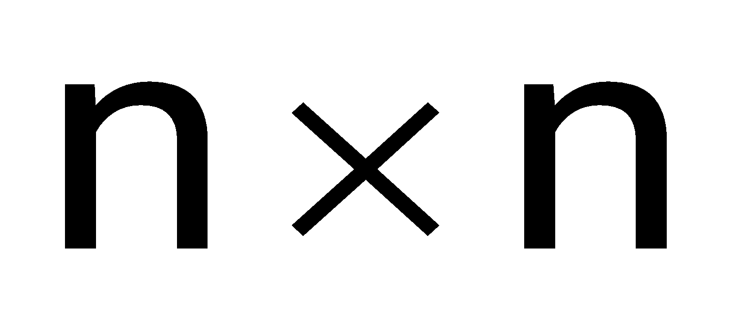
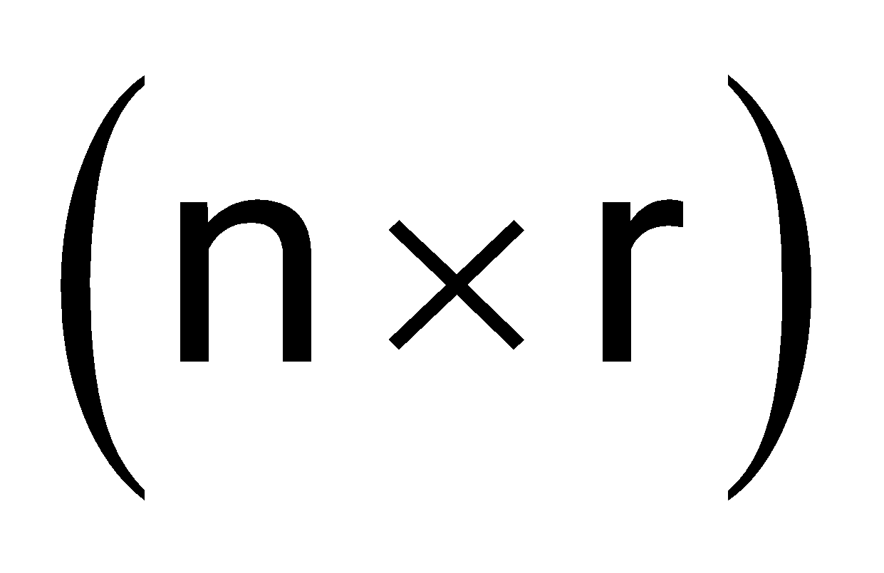
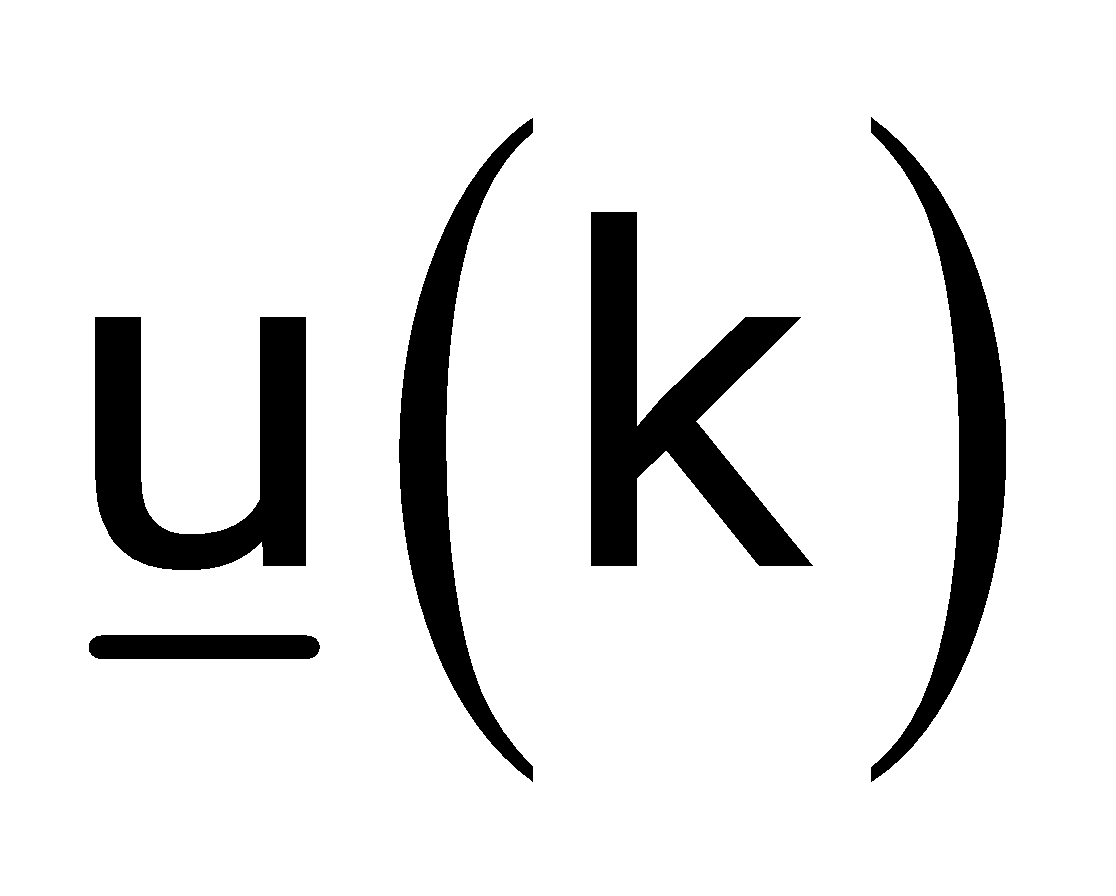
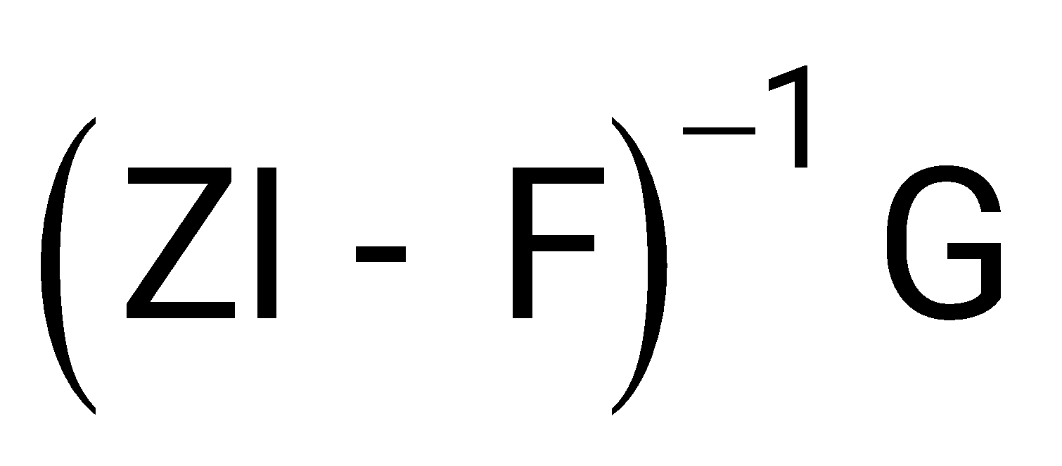
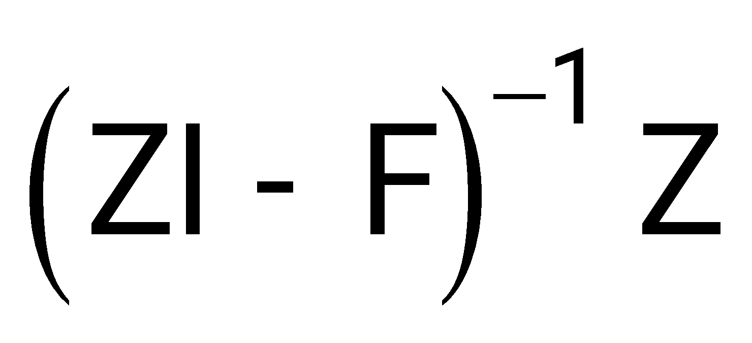
Sign in to UnlockA linear time-invariant discrete-time system is described by the vector matrix difference equation.

Where is the state vector, F is a constant matrix, G is a constant matrix and is the control vector. The state transition matrix of the system is given by inverse Z-transform of
(ZI – F)
(ZI – F) Z
Sign in to see the solution
Log in to view the explanation, track your attempts, and keep your progress.
Sign in to Unlock