Network Analysis
Transient Analysis
Practice questions from Transient Analysis.
67
Total0
Attempted0
Correct0
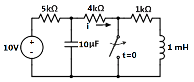
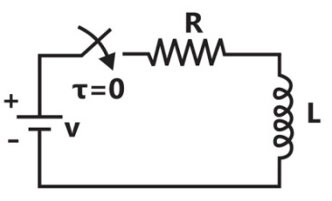
IncorrectIn the circuit given below, the switch was kept open for a sufficiently long time and is closed at time . The time constant (in seconds) of the circuit for is ________.


Sign in to see the solution
Log in to view the explanation, track your attempts, and keep your progress.
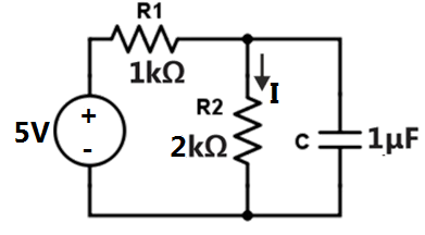
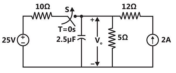
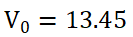
Sign in to UnlockIn the circuit shown below, switch S was closed for a long time. If the switch is opened at t=0, the maximum magnitude of the voltage in volts, is ________ (rounded off to the nearest integer).

Sign in to see the solution
Log in to view the explanation, track your attempts, and keep your progress.
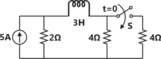
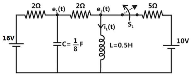
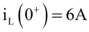
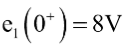
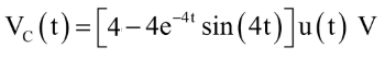
Sign in to UnlockThe switch was closed and was open for a long time. At , switch is opened and is closed, simultaneously. The value of , in amperes, is


Sign in to see the solution
Log in to view the explanation, track your attempts, and keep your progress.
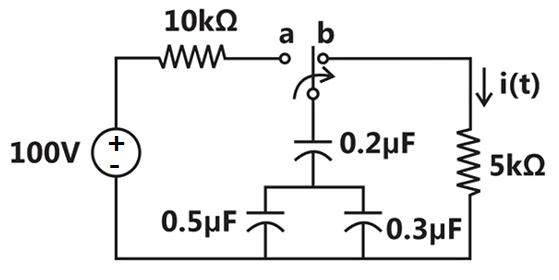
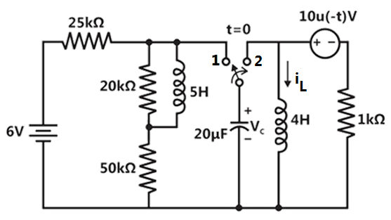
Sign in to UnlockThe switch in the circuit in the figure is in position for a long time and then moved to position at time .


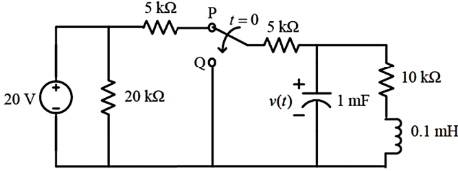
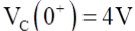
The value of at is


Sign in to see the solution
Log in to view the explanation, track your attempts, and keep your progress.
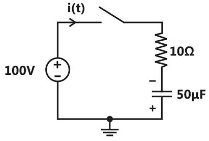
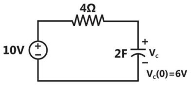
Sign in to UnlockIn the circuit shown in the figure, the switch is closed at time , while the capacitor is initially charged to (i.e., ).


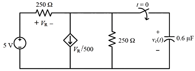
The time after which the voltage across the capacitor becomes zero (rounded off to three decimal places) is _______.

Sign in to see the solution
Log in to view the explanation, track your attempts, and keep your progress.
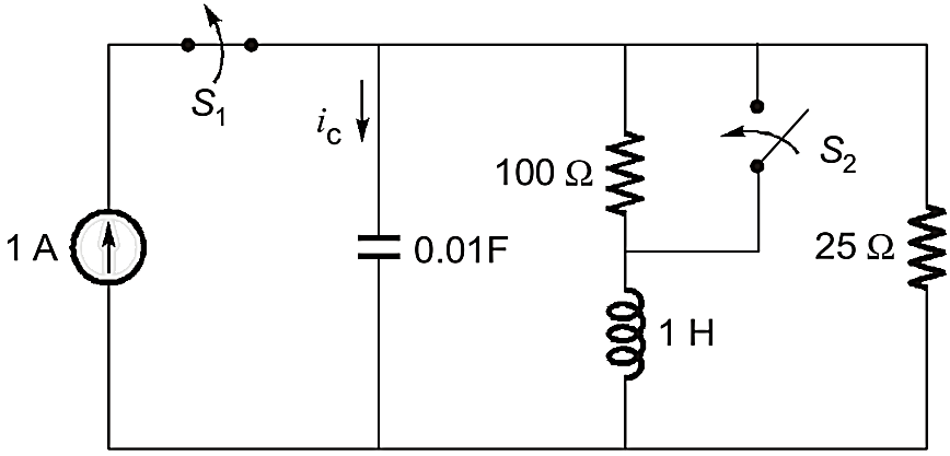
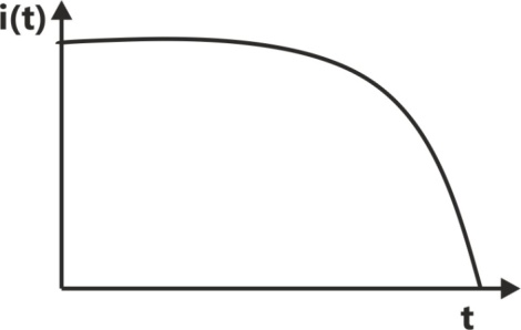
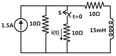
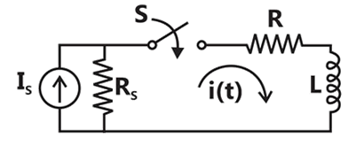
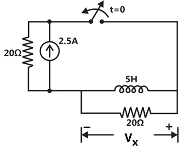
Sign in to UnlockThe circuit in the figure contains a current source driving a load having an inductor and a resistor in series, with a shunt capacitor across the load. The ammeter is assumed to have zero resistance. The switch is closed at time .
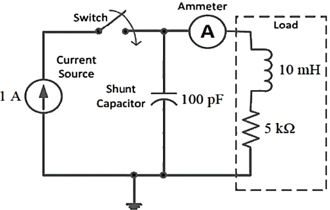
Initially, when the switch is open, the capacitor is discharged and the ammeter reads zero ampere. After the switch is closed, the ammeter reading keeps fluctuating for some time till it settles to a final steady value. The maximum ammeter reading that one will observe after the switch is closed (rounded off to two decimal places) is____________A.
Sign in to see the solution
Log in to view the explanation, track your attempts, and keep your progress.
Sign in to UnlockThe RC circuit shown below has a variable resistance R(t) given by the following expression:
for


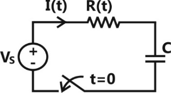
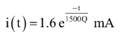
Where and C=1 F. We also given thatand the source voltage is. If the current at time t=0 is 1A, then the current I(t), in amperes, at time is ______ (rounded off to 2 decimal places)


Sign in to see the solution
Log in to view the explanation, track your attempts, and keep your progress.
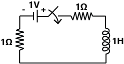
Sign in to UnlockFor the circuit given in the figure, the magnitude of the loop current (in amperes, correct to three decimal places) 0.5 second after closing the switch is ________
Sign in to see the solution
Log in to view the explanation, track your attempts, and keep your progress.
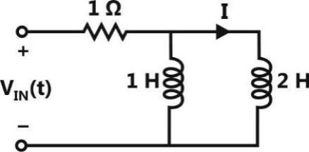
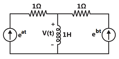
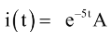
Sign in to UnlockIn the circuit shown, the voltage is described by:


Where t is in seconds. The time (in seconds) at which the current I in the circuit will reach the value 2 Amperes is ___________.
Sign in to see the solution
Log in to view the explanation, track your attempts, and keep your progress.
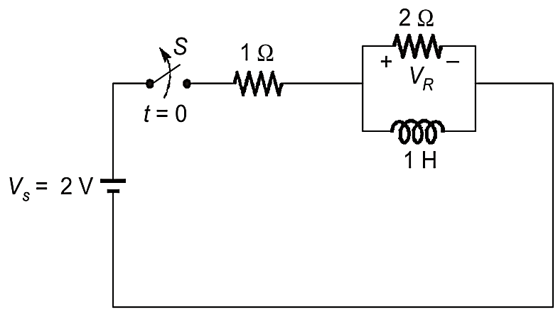
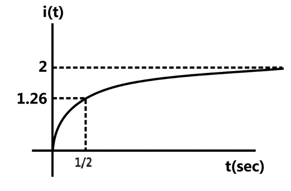
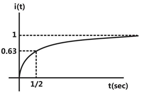
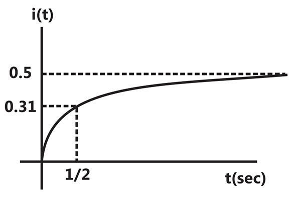
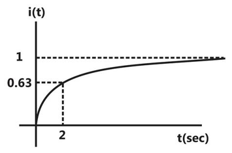
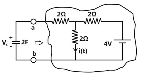
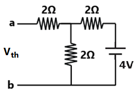
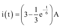
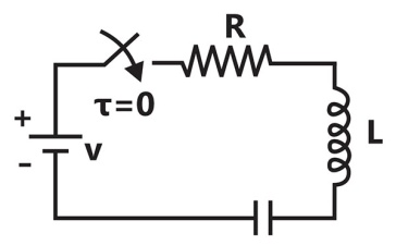
Sign in to UnlockThe switch in the circuit, shown in the figure, was open for a long time and is closed at t = 0.
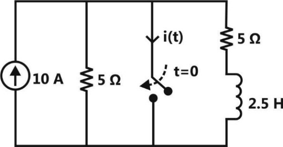
The current i (t) (in ampere) at t = 0.5 seconds is
Sign in to see the solution
Log in to view the explanation, track your attempts, and keep your progress.
Sign in to UnlockThe switch has been in position 1 for a long time and abruptly changes to position 2 at .
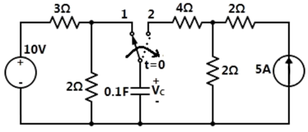
If time t is in seconds, the capacitor voltage (in volts) for t > 0 is given by


Sign in to see the solution
Log in to view the explanation, track your attempts, and keep your progress.
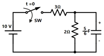
Sign in to UnlockAssume that the circuit in the figure has reached the steady state before time t = 0 when the 3 Ω resistor suddenly burns out, resulting in an open circuit. The current i(t) (in ampere) at is ________.
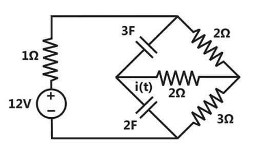
Sign in to see the solution
Log in to view the explanation, track your attempts, and keep your progress.
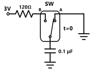
Sign in to UnlockIn the circuit shown, the switch SW is thrown from position A to position B at time t = 0. The energy (in μJ) taken from the 3 V source to charge the 0.1 μF capacitor from 0 V to 3 V is
Sign in to see the solution
Log in to view the explanation, track your attempts, and keep your progress.
Sign in to UnlockThe damping ratio of a series RLC circuit can be expressed as


Sign in to see the solution
Log in to view the explanation, track your attempts, and keep your progress.
Sign in to UnlockIn the circuit shown, switch SW is closed at t = 0. Assuming zero initial conditions, the value of (in Volts) at t = 1 sec is ________.

Sign in to see the solution
Log in to view the explanation, track your attempts, and keep your progress.
Sign in to UnlockAn LC tank circuit consists of an ideal capacitor C connected in parallel with a coil of inductance L having an internal resistance R. The resonant frequency of the tank circuit is


Sign in to see the solution
Log in to view the explanation, track your attempts, and keep your progress.
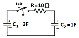
Sign in to UnlockIn the circuit shown, the initial voltages across the capacitors and are 1 V and 3 V, respectively. The switch is closed at time t=0. The total energy dissipated (in Joules) in the resistor R until steady state is reached, is __________.


Sign in to see the solution
Log in to view the explanation, track your attempts, and keep your progress.
Sign in to UnlockIn the circuit shown in the figure, the value of capacitor C (in mF) needed to have critically damped response i(t) is_________.
Sign in to see the solution
Log in to view the explanation, track your attempts, and keep your progress.
Sign in to UnlockIn the figure shown, the ideal switch has been open for a long time. If it is closed at t=0, then the magnitude of the current (in mA) through the 4kΩ resistor at is ___________.
Sign in to see the solution
Log in to view the explanation, track your attempts, and keep your progress.
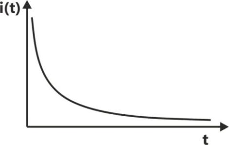
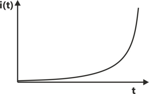
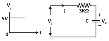
Sign in to Unlockn the figure shown, the capacitor is initially uncharged. Which one of the following expressions describes the current I(t) (in mA) for ?


Sign in to see the solution
Log in to view the explanation, track your attempts, and keep your progress.
Sign in to UnlockA series RC circuit is connected to a DC voltage source at time t = 0. The relation between the source voltage, the resistance R, the capacitance C, and the current i(t) is given below:

.

Which one of the following represents the current i(t)?
Sign in to see the solution
Log in to view the explanation, track your attempts, and keep your progress.
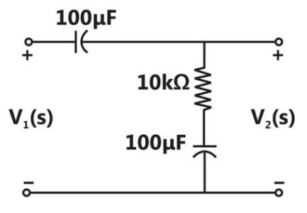
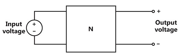
Sign in to UnlockConsider the building block called ‘Network N’ shown in the figure. Let C = 100 µF and R= 10kΩ.
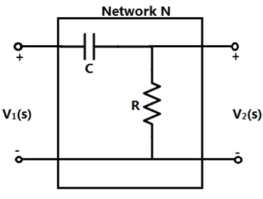
Two such blocks are connected in cascade, as shown in the figure.
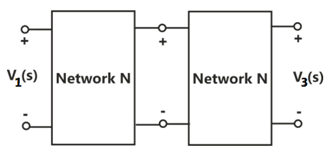
The transfer function of the cascaded network is


Sign in to see the solution
Log in to view the explanation, track your attempts, and keep your progress.
Sign in to UnlockIn the circuit shown in the figure, the value of (in Volts) for is ______.

Sign in to see the solution
Log in to view the explanation, track your attempts, and keep your progress.
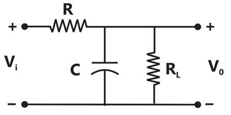
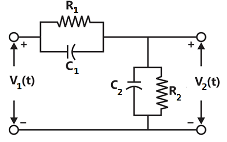
Sign in to UnlockThe transfer function of the circuit shown below is


Sign in to see the solution
Log in to view the explanation, track your attempts, and keep your progress.
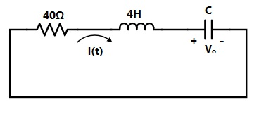
Sign in to UnlockIn the circuit shown below, the initial charge on the capacitor is 2.5mC, with the voltage polarity as indicated. The switch is closed at t=0. The current i(t) at a time t after the switch is closed is?


Sign in to see the solution
Log in to view the explanation, track your attempts, and keep your progress.
Sign in to UnlockIn the circuit shown, the switch S is open for a long time and is closed at . The current i(t) for is


Sign in to see the solution
Log in to view the explanation, track your attempts, and keep your progress.
Sign in to UnlockIf the transfer function of the following network is, the value of the load resistance is


Sign in to see the solution
Log in to view the explanation, track your attempts, and keep your progress.
Sign in to UnlockThe switch in the circuit shown was on position ‘a’ for a long time, and is moved to position ‘b’ at time t=0. The current i(t) for t>0 is given by


Sign in to see the solution
Log in to view the explanation, track your attempts, and keep your progress.
Sign in to UnlockThe time domain behaviour of an RL circuit is represented by

For an initial current of , the steady state value of the current is given by


Sign in to see the solution
Log in to view the explanation, track your attempts, and keep your progress.
Sign in to UnlockIn the following circuit, the switch S is closed at t=0. The rate of change of current is given by

0


Sign in to see the solution
Log in to view the explanation, track your attempts, and keep your progress.
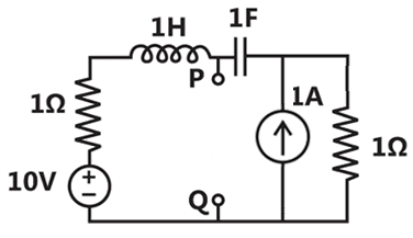
Sign in to UnlockThe Thevenin’s equivalent impedance between the nodes P and Q in the following circuit is

1


Sign in to see the solution
Log in to view the explanation, track your attempts, and keep your progress.
Sign in to UnlockThe driving point impedance of the following network
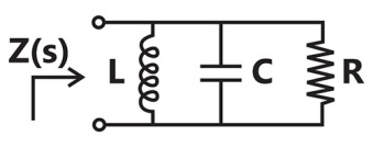
Is given by.The component values are

L = 5 H, , C = 0.1F

L = 0.1 H, , C = 5F
L = 5 H, , C = 0.1F

L = 0.1 H, , C = 5F
Sign in to see the solution
Log in to view the explanation, track your attempts, and keep your progress.
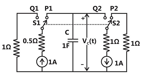
Sign in to UnlockThe circuit shown in the figure is used to charge the capacitor C alternately from two current sources as indicated. The Switches and are mechanically coupled and connected as follows:


For ,

(n = 0, 1, 2,…) to and to


For ,

(n = 0, 1, 2,…) to and to .


Assume that the capacitor has zero initial charge. Given that u(t) is a unit step function, the voltage across the capacitor is given by


Sign in to see the solution
Log in to view the explanation, track your attempts, and keep your progress.
Sign in to Unlock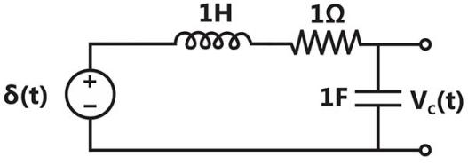
The following series RLC circuit with zero initial conditions is excited by a unit impulse function

For t > 0, the output voltage is


Sign in to see the solution
Log in to view the explanation, track your attempts, and keep your progress.
Sign in to UnlockThe following series RLC circuit with zero initial conditions is excited by a unit impulse function
For t > 0, the voltage across the resistor is


Sign in to see the solution
Log in to view the explanation, track your attempts, and keep your progress.
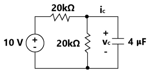
Sign in to UnlockIn the circuit shown, is 0 volts at t=0 sec. For t > 0, the capacitor current , where t is in seconds, is given by


Sign in to see the solution
Log in to view the explanation, track your attempts, and keep your progress.
Sign in to UnlockThe first and the last critical frequencies (singularities) of a driving point impedance function of a passive network having two kinds of elements, are a pole and a zero respectively. The above property will be satisfied by
Sign in to see the solution
Log in to view the explanation, track your attempts, and keep your progress.
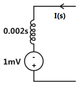
Sign in to UnlockA 2mH inductor with some initial current can be represented as shown below, where s is the Laplace Transform Variable. The value of initial current is:
Sign in to see the solution
Log in to view the explanation, track your attempts, and keep your progress.
Sign in to UnlockIn the figure shown below, assume that all the capacitors are initially uncharged. If Volts, is given by


Volts

Volts

8u(t) Volts
8 Volts
Sign in to see the solution
Log in to view the explanation, track your attempts, and keep your progress.
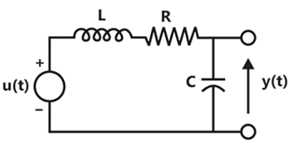
Sign in to UnlockThe condition on R, L and C such that the step response y(t) in figure has no oscillations, is


Sign in to see the solution
Log in to view the explanation, track your attempts, and keep your progress.
Sign in to UnlockThe first and the last critical frequency of an RC-driving point impedance function must respectively be
Sign in to see the solution
Log in to view the explanation, track your attempts, and keep your progress.
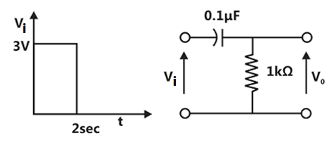
Sign in to UnlockA square pulse of 3 volts amplitude is applied to C-R circuit shown in figure. The capacitor is initially uncharged. The output voltage at time t=2 sec is

Sign in to see the solution
Log in to view the explanation, track your attempts, and keep your progress.
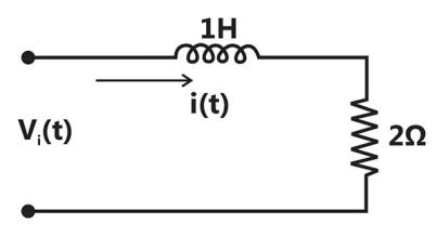
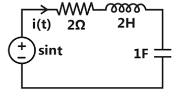
Sign in to UnlockFor the R-L circuit shown in Figure, the input voltage. The current i(t) is

Sign in to see the solution
Log in to view the explanation, track your attempts, and keep your progress.
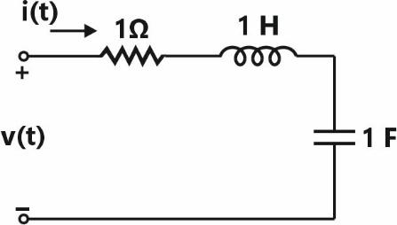
Sign in to UnlockThe circuit shown in figure has initial current through the inductor and an initial voltage across the capacitor. For input v(t) = u(t), the Laplace transform of the current i(t) for is


Sign in to see the solution
Log in to view the explanation, track your attempts, and keep your progress.
Sign in to UnlockThe differential equation for the current i(t) in the circuit is


Sign in to see the solution
Log in to view the explanation, track your attempts, and keep your progress.
Sign in to UnlockAssume that the switch S is in position 1 for a long time and thrown to position 2 at t = 0.
At , the current is


zero
Sign in to see the solution
Log in to view the explanation, track your attempts, and keep your progress.
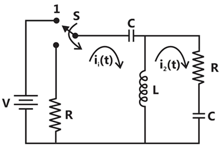
Sign in to UnlockAssume that the switch S is in position 1 for a long time and thrown to position 2 at t = 0.
and are the Laplace transforms of and respectively. The equations for the loop currents and for the circuit shown above, after the switch is brought from position 1 to position 2 at t = 0, are


Sign in to see the solution
Log in to view the explanation, track your attempts, and keep your progress.
Sign in to UnlockAn input voltage
is applied to a series combination of resistance R = 1Ω and an inductance L = 1H. The resulting steady state current i(t) in ampere is


Sign in to see the solution
Log in to view the explanation, track your attempts, and keep your progress.
Sign in to UnlockIn figure, the switch was closed for a long time before opening at t = 0. The voltage at is .

Sign in to see the solution
Log in to view the explanation, track your attempts, and keep your progress.
Sign in to UnlockThe switch in figure has been in position 1 for a long time and is then moved to position 2 at t = 0.
(a) Determine and


(b) Determine at


(c) Determine for t > 0
for t > 0

Sign in to see the solution
Log in to view the explanation, track your attempts, and keep your progress.
Sign in to UnlockThe circuit shown in figure is operating in steady-state with switch closed. The switch is opened at t=0.

voltage across the capacitor for all t > 0.
voltage across the capacitor for all t > 0.

Sign in to see the solution
Log in to view the explanation, track your attempts, and keep your progress.
Sign in to UnlockIn the circuit of Figure, the voltage v(t) is


Sign in to see the solution
Log in to view the explanation, track your attempts, and keep your progress.
Sign in to UnlockFor the circuit in Figure
Thevenin’s equivalent of the sub circuit faced by the capacitance across the terminals a, b.
For , given


For
For
Sign in to see the solution
Log in to view the explanation, track your attempts, and keep your progress.
Sign in to UnlockFor the circuit in Figure, write the state equations using and as state variables.


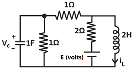
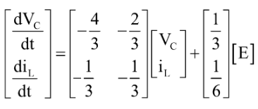

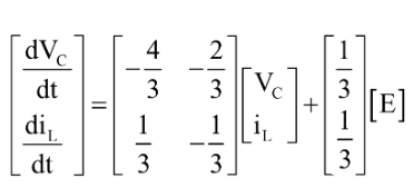
None of these
Sign in to see the solution
Log in to view the explanation, track your attempts, and keep your progress.
Sign in to UnlockThe network N in Figure consists only of two elements: a resistor of and an inductor of L Henry. A 5 V source is connected at the input at t = 0 seconds. The Inductor current is zero at t = 0. The output voltage is found to be ,


L= 1 H
Voltage transfer function of the network
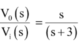

Impulse response of the network

Sign in to see the solution
Log in to view the explanation, track your attempts, and keep your progress.
Sign in to UnlockIn the circuit of Figure, the switch‘S’has remained open for a long time.The switch closes instantaneously at t = 0.
for


for


for


at

Sign in to see the solution
Log in to view the explanation, track your attempts, and keep your progress.
Sign in to UnlockIn the circuit of the figure is the energy absorbed by the resistor in the time interval is


Sign in to see the solution
Log in to view the explanation, track your attempts, and keep your progress.
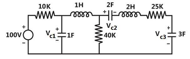
Sign in to UnlockThe voltage, and across the capacitors in the capacitors in the circuit in the given figure, under steady state, are respectively.


Sign in to see the solution
Log in to view the explanation, track your attempts, and keep your progress.
Sign in to UnlockIn the circuit shown in the figure is (a) – (c), assuming initial voltage and capacitors and currents through the inductors to be zero at the time of switching (t=0), then at any time.
(a)
(b)
(c)
(1) Current increases monotonically with time
(2) Current decreases monotonically with time
(3) Current remains constants at V/R
(4) Current first increases then decreases
(5) No current can ever flow
Sign in to see the solution
Log in to view the explanation, track your attempts, and keep your progress.
Sign in to UnlockA DC voltage source is connected across a series R-L-C circuit. Under steady-state conditions, the applied DC voltage drops entirely across the
Sign in to see the solution
Log in to view the explanation, track your attempts, and keep your progress.
Sign in to UnlockConsider a DC voltage source connected to a series R-C circuit. When the steady-state reaches, the ratio of the energy stored in the capacitor to the total energy supplied by the voltage source, is equal to
Sign in to see the solution
Log in to view the explanation, track your attempts, and keep your progress.
Sign in to UnlockA ramp voltage, volts, is applied to an RC differentiating circuit with and. The maximum output voltage is


Sign in to see the solution
Log in to view the explanation, track your attempts, and keep your progress.
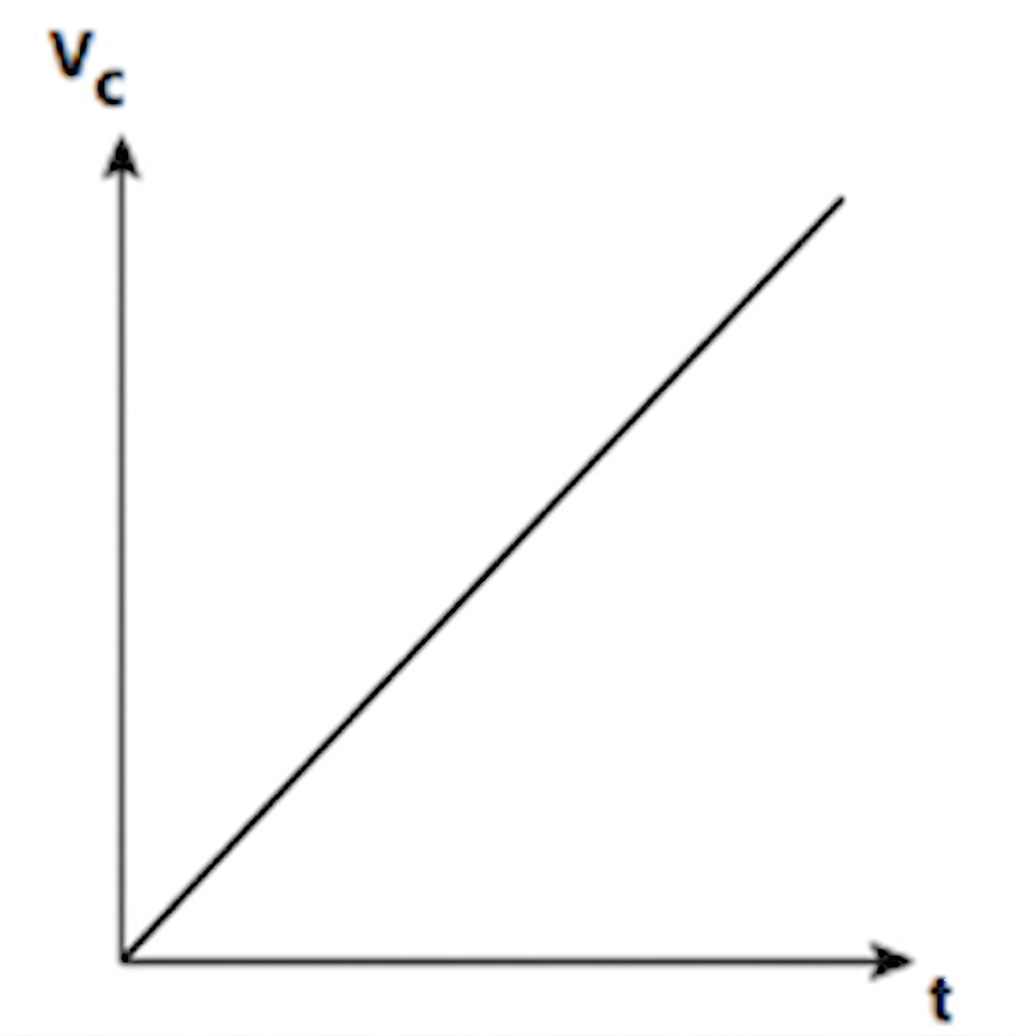
Sign in to UnlockIn the following circuit the capacitance varies as, where K is a constant equal to 0.5 Farads/coulomb and Q, the charge on the capacitor in Coulombs. Determine the current through the circuit
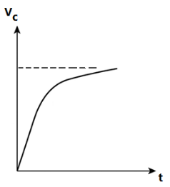
and sketch the voltage waveform across the capacitor for a step input as shown in figure.


Sign in to see the solution
Log in to view the explanation, track your attempts, and keep your progress.
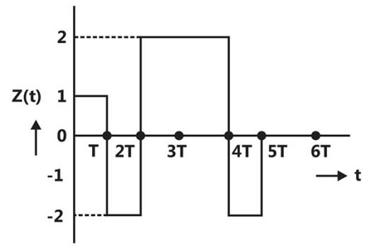
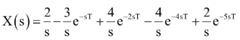
Sign in to Unlock(a) Find the Laplace transform of the waveform x(t) shown in figure.
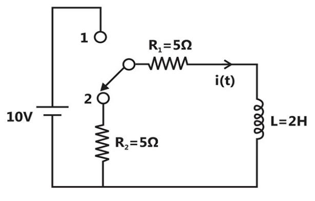
(b) The network shown in figure is initially under steady state condition with the switch in position 1. The switch is moved from position 1 to position 2 at. Calculate the current i(t) through after switching.


Sign in to see the solution
Log in to view the explanation, track your attempts, and keep your progress.
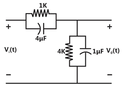
Sign in to UnlockFor the compensated attenuator of figure, the impulse response under the condition is:


Sign in to see the solution
Log in to view the explanation, track your attempts, and keep your progress.
Sign in to UnlockOf the four networks,, , and of figure, the networks having identical driving point functions are


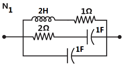
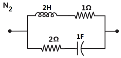
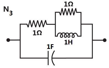
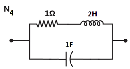
and
and
and
and
Sign in to see the solution
Log in to view the explanation, track your attempts, and keep your progress.
Sign in to UnlockThe necessary and sufficient condition for a rational function of s. T(s) to be driving point impedance of an RC network is that all poles and zeros should be
Sign in to see the solution
Log in to view the explanation, track your attempts, and keep your progress.
Sign in to Unlock