Network Analysis
Sinusoidal Steady State Analysis
Practice questions from Sinusoidal Steady State Analysis.
75
Total0
Attempted0
Correct0
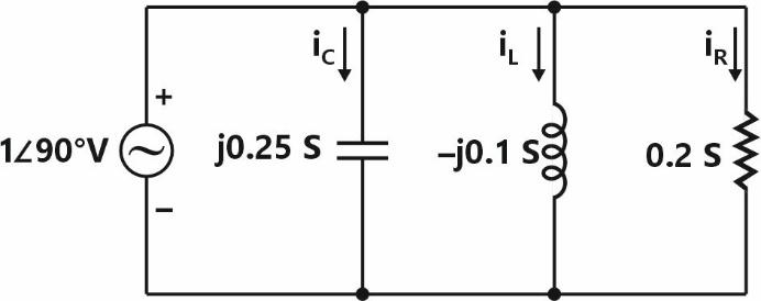
IncorrectLet , and be the currents flowing through the capacitor, inductor, and resistor, respectively, in the circuit given below. The AC admittances are given in Siemens (S).


Which one of the following is TRUE?




Sign in to see the solution
Log in to view the explanation, track your attempts, and keep your progress.
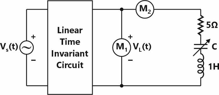
Sign in to UnlockIn the circuit below, is an ideal AC voltmeter and is an ideal AC ammeter. The source voltage (in Volts) is .



What should be the value of the variable capacitor such that the RMS readings on and are 25 V and 5 A, respectively?




Insufficient information to find C
Sign in to see the solution
Log in to view the explanation, track your attempts, and keep your progress.
Sign in to UnlockA series RLC circuit has a quality factor of 1000 at a center frequency of . The possible values of and are




and


and

and

and

Sign in to see the solution
Log in to view the explanation, track your attempts, and keep your progress.
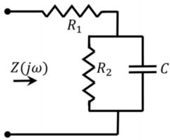
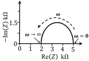
Sign in to UnlockFor the circuit shown, the locus of the impedance is plotted as increases from zero to infinity. The values of and are:








Sign in to see the solution
Log in to view the explanation, track your attempts, and keep your progress.
Sign in to UnlockConsider the circuit shown in the figure with input in volts. The sinusoidal steady state current flowing through the circuit is shown graphically (where is in seconds). The circuit element can be _______.




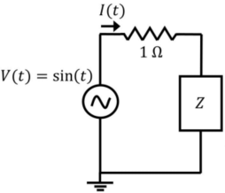
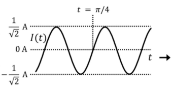
a capacitor of

an inductor of

a capacitor of

an inductor of

Sign in to see the solution
Log in to view the explanation, track your attempts, and keep your progress.
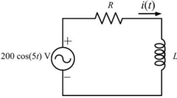
Sign in to UnlockThe current in the RL-circuit shown below is .

The value of the inductor (rounded off to two decimal places) is _____H.
Sign in to see the solution
Log in to view the explanation, track your attempts, and keep your progress.
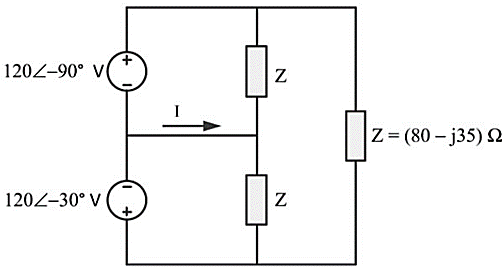
Sign in to UnlockThe current I in the given network is

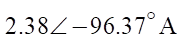
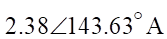
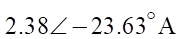
Sign in to see the solution
Log in to view the explanation, track your attempts, and keep your progress.
Sign in to UnlockIn the circuit shown, ifVolts, R=1kΩ and C=1µF, then the steady state current i(t), in milliamperes (mA) is

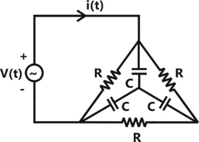




Sign in to see the solution
Log in to view the explanation, track your attempts, and keep your progress.
Sign in to UnlockFor the circuit given in the figure, the voltage (in volts) across the capacitor is

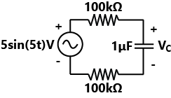




Sign in to see the solution
Log in to view the explanation, track your attempts, and keep your progress.
Sign in to UnlockIn the circuit shown, the positive angular frequency (in radians per second) at which the magnitude of the phase difference between the voltages and equals radians, is



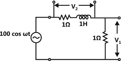
Angle of must befor which real & imaginary part must be equal or



Sign in to see the solution
Log in to view the explanation, track your attempts, and keep your progress.
Sign in to UnlockThe figure shows an RLC circuit excited by the sinusoidal voltage 100 cos (3t) Volts, where t is in seconds. The ratio is _________________.

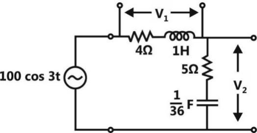
Sign in to see the solution
Log in to view the explanation, track your attempts, and keep your progress.
Sign in to UnlockIn the circuit shown, V is a sinusoidal voltage source. The current I is in phase with voltage V. The ratio is ______________.

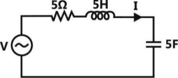
Sign in to see the solution
Log in to view the explanation, track your attempts, and keep your progress.
Sign in to UnlockThe figure shows an RLC circuit with a sinusoidal current source.
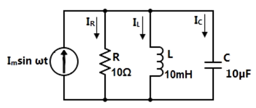
At resonance, the ratio , i.e., the ratio of the magnitudes of the inductor current phasor and the resistor current phasor, is ________.

Sign in to see the solution
Log in to view the explanation, track your attempts, and keep your progress.
Sign in to UnlockIn the RLC circuit shown, the input voltage is given by . The output voltage V₀(t) is

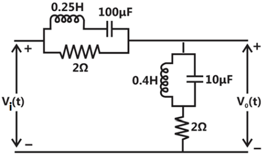




Sign in to see the solution
Log in to view the explanation, track your attempts, and keep your progress.
Sign in to UnlockIn the circuit shown, at resonance, the amplitude of the sinusoidal voltage (in Volts) across the capacitor is ________.
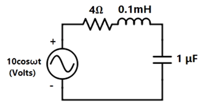
Sign in to see the solution
Log in to view the explanation, track your attempts, and keep your progress.
Sign in to UnlockIn the given circuit, the maximum power (in Watts) that can be transferred to the load is _______.

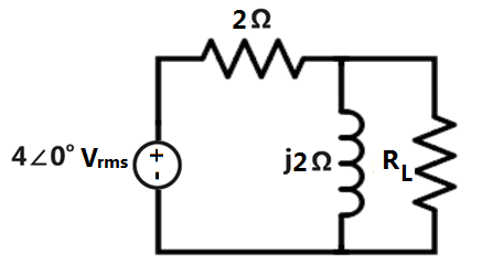
Sign in to see the solution
Log in to view the explanation, track your attempts, and keep your progress.
Sign in to UnlockThe voltage ( ) across the capacitor (in Volts) in the network shown is ____.
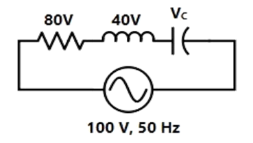
Sign in to see the solution
Log in to view the explanation, track your attempts, and keep your progress.
Sign in to UnlockIn the circuit shown, the average value of the voltage (in Volts) in steady state condition is____.

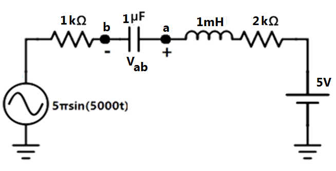
Sign in to see the solution
Log in to view the explanation, track your attempts, and keep your progress.
Sign in to UnlockAt very high frequencies, the peak output voltage (in Volts) is ________.

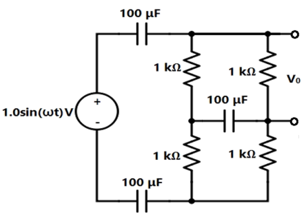
Sign in to see the solution
Log in to view the explanation, track your attempts, and keep your progress.
Sign in to UnlockIn the circuit shown, the current I flowing through the 50 Ω resistor will be zero if the value of capacitor C (in μF) is ______.
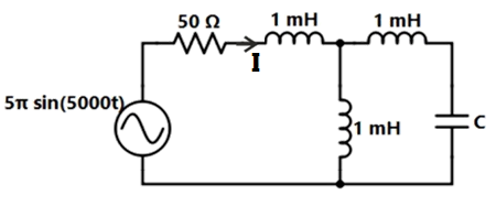
Sign in to see the solution
Log in to view the explanation, track your attempts, and keep your progress.
Sign in to UnlockThe maximum power transfer between two cascaded sections of an electrical network, the relationship between the output impedanceof the first section to the input impedance of the second section is






Sign in to see the solution
Log in to view the explanation, track your attempts, and keep your progress.
Sign in to UnlockA 230 V RMS source supplies power to two loads connected in parallel. The first load draws 10 kW at 0.8 leading power factor and the second one draws 10kVA at 0.8 lagging power factor. The complex power delivered by the source is
kVA

kVA

kVA

kVA

Sign in to see the solution
Log in to view the explanation, track your attempts, and keep your progress.
Sign in to UnlockA series LCR circuit is operated at a frequency different from its resonant frequency. The operating frequency is such that the current leads the supply voltage. The magnitude of current is half the value at resonance. If the values of L, C and R are 1 H, 1 F and 1 Ω, respectively, the operating angular frequency (in rad/s) is ________.
Sign in to see the solution
Log in to view the explanation, track your attempts, and keep your progress.
Sign in to UnlockIn the circuit shown in the figure, the value of node voltage is
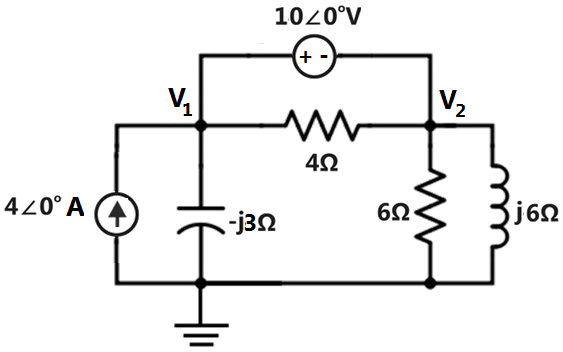
Sign in to see the solution
Log in to view the explanation, track your attempts, and keep your progress.
Sign in to UnlockIn the circuit shown in the figure, the angular frequency ω (in rad/s), at which the Norton equivalent impedance as seen from terminals b-b′ is purely resistive, is _________.
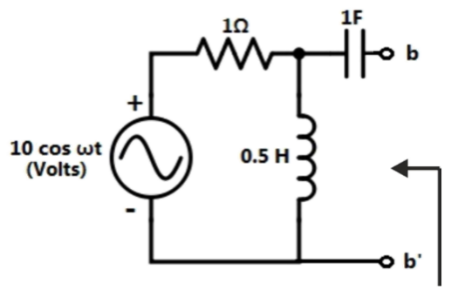
Sign in to see the solution
Log in to view the explanation, track your attempts, and keep your progress.
Sign in to UnlockThe steady state output of the circuit shown in the figure is given by . If the amplitude, then the frequency ω is


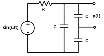




Sign in to see the solution
Log in to view the explanation, track your attempts, and keep your progress.
Sign in to UnlockA source has an internal impedance of. If a purely resistive load connected to this source has to extract the maximum power out of the source, its value in should be



Sign in to see the solution
Log in to view the explanation, track your attempts, and keep your progress.
Sign in to UnlockIn the circuit shown below, if the source voltage then the Thevenin’s equivalent voltage in Volts as seen by the load resistance is


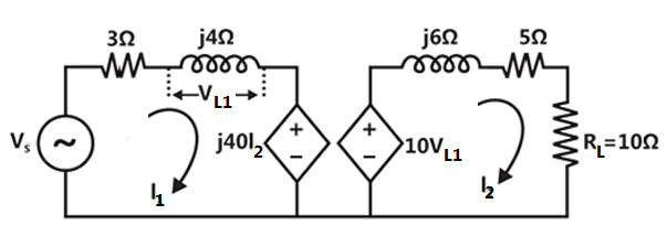




Sign in to see the solution
Log in to view the explanation, track your attempts, and keep your progress.
Sign in to UnlockThe average power delivered to an impedance by a current is


Sign in to see the solution
Log in to view the explanation, track your attempts, and keep your progress.
Sign in to UnlockIn the circuit shown below, the current through the inductor is
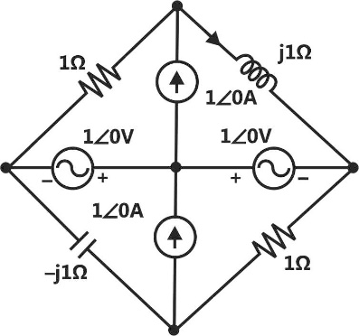




Sign in to see the solution
Log in to view the explanation, track your attempts, and keep your progress.
Sign in to UnlockThe circuit shown below is driven by a sinusoidal input. The steady state output is


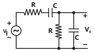




Sign in to see the solution
Log in to view the explanation, track your attempts, and keep your progress.
Sign in to UnlockIn the circuit shown below, the current I is equal to
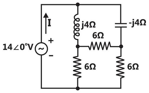




Sign in to see the solution
Log in to view the explanation, track your attempts, and keep your progress.
Sign in to UnlockFor parallel RLC circuit, which one of the following statements is NOT correct?
Sign in to see the solution
Log in to view the explanation, track your attempts, and keep your progress.
Sign in to UnlockThe current I in the circuit shown is
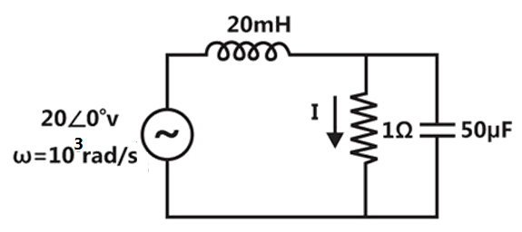
Sign in to see the solution
Log in to view the explanation, track your attempts, and keep your progress.
Sign in to UnlockAn AC source of RMS voltage 20 V with internal impedance feeds a load of impedance in the figure below. The reactive power consumed by the load is


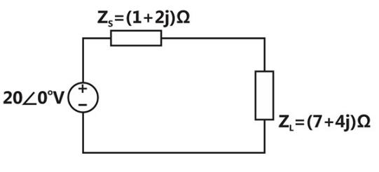
Sign in to see the solution
Log in to view the explanation, track your attempts, and keep your progress.
Sign in to UnlockAn independent voltage source in series with an impedance delivers a maximum average power to a load impedance when






Sign in to see the solution
Log in to view the explanation, track your attempts, and keep your progress.
Sign in to UnlockThe RC circuit shown in the figure is
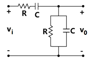
Sign in to see the solution
Log in to view the explanation, track your attempts, and keep your progress.
Sign in to UnlockTwo series resonant filters are as shown in the figure. Let the 3-dB bandwidth of Filter 1 be and that of Filter 2 be The value of is



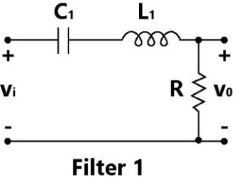
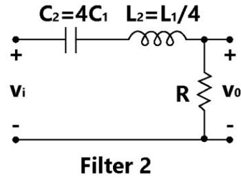
4
1


Sign in to see the solution
Log in to view the explanation, track your attempts, and keep your progress.
Sign in to Unlockin the AC network shown in the figure, the phasor voltage (in Volts) is

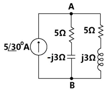
0



Sign in to see the solution
Log in to view the explanation, track your attempts, and keep your progress.
Sign in to UnlockA negative resistance is connected to a passive network N having driving point impedance as shown below. For to be positive real,



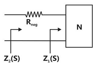
,


,

,

,

Sign in to see the solution
Log in to view the explanation, track your attempts, and keep your progress.
Sign in to UnlockIn a series RLC circuit, L = 1H and . The resonant frequency is






Sign in to see the solution
Log in to view the explanation, track your attempts, and keep your progress.
Sign in to UnlockFor the circuit in figure the instantaneous current is

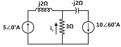
Amps

Amps

Amps

Amps

Sign in to see the solution
Log in to view the explanation, track your attempts, and keep your progress.
Sign in to UnlockThe circuit shown in figure, with, , C = 3F has input voltage . The resulting current i(t) is



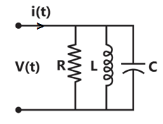
Sign in to see the solution
Log in to view the explanation, track your attempts, and keep your progress.
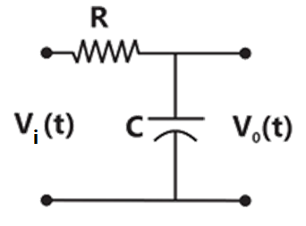
Sign in to UnlockFor the circuit shown in Figure, the time constant RC=1ms. The input voltage is. The output voltage is equal to






Sign in to see the solution
Log in to view the explanation, track your attempts, and keep your progress.
Sign in to UnlockThe transfer function of an R-L-C circuit is given by. The Quality factor (Q-factor) of this circuit is


Sign in to see the solution
Log in to view the explanation, track your attempts, and keep your progress.
Sign in to UnlockConsider the following statements and


: At the resonant frequency the impedance of a series R-L-C circuit is zero.
: In a parallel G-L-C circuit, increasing the conductance G results in increase in its Q factor.
Which one of the following is correct?
is FALSE and is TRUE
both and are TRUE
is TRUE and is FALSE
both and are FALSE
Sign in to see the solution
Log in to view the explanation, track your attempts, and keep your progress.
Sign in to UnlockA source of angular frequency 1rad/sec has a source impedance consisting of 1Ω resistance in series with 1 H inductance. The load that will obtain the maximum power transfer is
Sign in to see the solution
Log in to view the explanation, track your attempts, and keep your progress.
Sign in to UnlockA series RLC circuit has a response frequency of 1 KHz and a quality factor Q = 100. If each R, L and C is doubled from its original value, the new Q of the circuit is
Sign in to see the solution
Log in to view the explanation, track your attempts, and keep your progress.
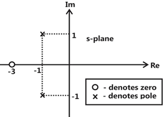
Sign in to UnlockThe driving point impedance Z(s) of a network has the pole-zero locations as shown in figure. If Z(0) = 3, then Z(s) is




Sign in to see the solution
Log in to view the explanation, track your attempts, and keep your progress.
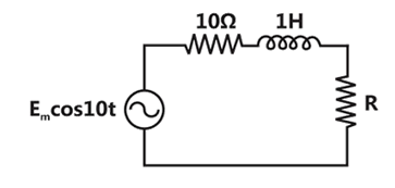
Sign in to UnlockIn figure shown below, the value of the load resistor R which maximizes the power delivered to it is
Sign in to see the solution
Log in to view the explanation, track your attempts, and keep your progress.
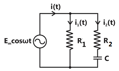
Sign in to UnlockWhen the angular frequency in figure is varied from 0 to , the locus of the current phasor is given by


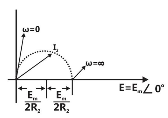
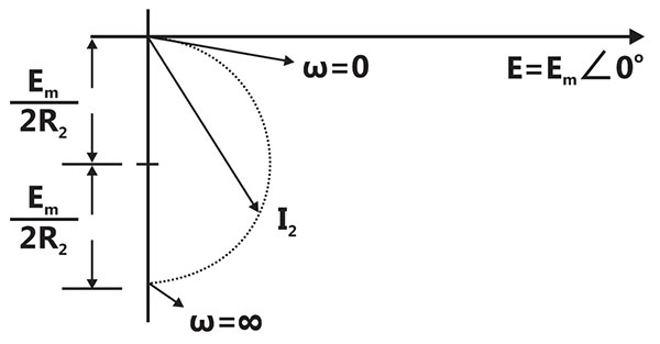
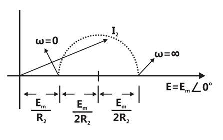
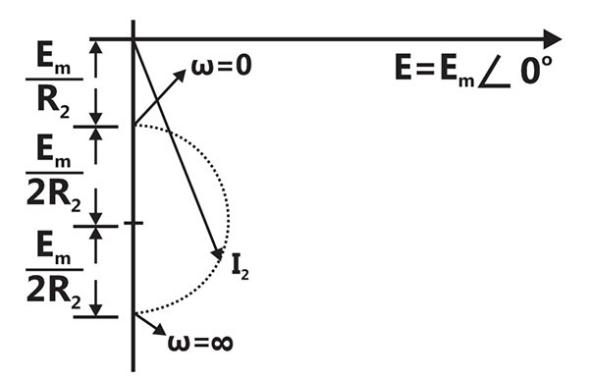
Sign in to see the solution
Log in to view the explanation, track your attempts, and keep your progress.
Sign in to UnlockFor the circuit shown in Figure, determine the phasors and


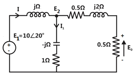



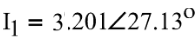
Sign in to see the solution
Log in to view the explanation, track your attempts, and keep your progress.
Sign in to UnlockThe circuit of Figure represents a
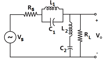
Sign in to see the solution
Log in to view the explanation, track your attempts, and keep your progress.
Sign in to UnlockIn Figure, the steady state output voltage corresponding to the input voltage is

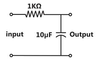




Sign in to see the solution
Log in to view the explanation, track your attempts, and keep your progress.
Sign in to UnlockFor the circuit in Figure, which is in steady state
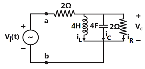
at which the magnitude of the impedance across terminals a and b reaches a maximum.

Given .


Impedance across a, b at the frequency
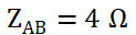

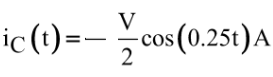
Sign in to see the solution
Log in to view the explanation, track your attempts, and keep your progress.
Sign in to UnlockThe Thevenin’s equivalent voltage appearing between the terminals A and B of the network shown in Figure is given by

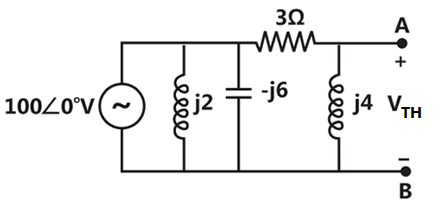




Sign in to see the solution
Log in to view the explanation, track your attempts, and keep your progress.
Sign in to UnlockFor the network shown in Figure, evaluate the magnitude of the current I flowing through the resistor using superposition theorem.

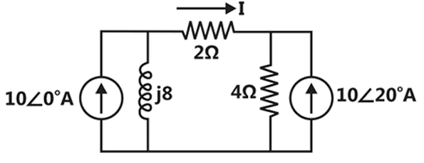
Sign in to see the solution
Log in to view the explanation, track your attempts, and keep your progress.
Sign in to UnlockA coil with a quality factor (Q) of 10 is put in series with capacitor of , and the combination is found to draw maximum current when a sinusoidal voltage of frequency 50 Hz is applied. A second capacitor is now in parallel with the circuit. What should be the capacitance of for combined circuit to act purely as a resistance for a sinusoidal excitation at a frequency of 100Hz? Calculate the RMS current drawn by the combined circuit at 100 Hz if the applied voltage is 100 V(RMS).




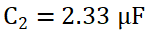
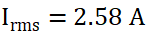
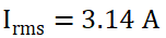
Sign in to see the solution
Log in to view the explanation, track your attempts, and keep your progress.
Sign in to UnlockThe parallel RLC circuit shown in Figure is in resonance. In this circuit
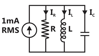




Sign in to see the solution
Log in to view the explanation, track your attempts, and keep your progress.
Sign in to UnlockDetermine the frequency of resonance and the resonant impedance of the parallel circuit shown in figure. What happens when ?

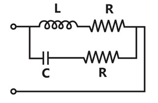
At
Impedance becomes frequency dependent and circuit resonates at infinite number of frequencies
Resonance frequency

Resonant impedance

At
Impedance becomes frequency independent and circuit resonates at infinite number of frequencies
Sign in to see the solution
Log in to view the explanation, track your attempts, and keep your progress.
Sign in to UnlockA voltage source of internal impedance supplies power to a load of impedance in which only is variable. Determine the value of for maximum power transfer from the source to the load. Also, find the numerical value of if the source impedance is (purely resistive) and is .





Sign in to see the solution
Log in to view the explanation, track your attempts, and keep your progress.
Sign in to UnlockIn the circuit of the figure is the equivalent impedance seen across terminals a, b is
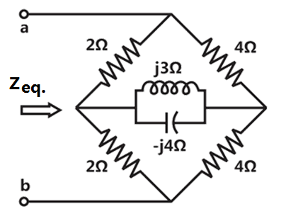



None of the above
Sign in to see the solution
Log in to view the explanation, track your attempts, and keep your progress.
Sign in to Unlock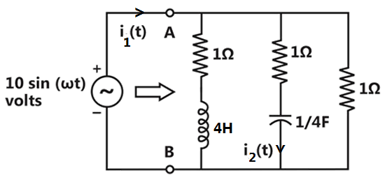
In the circuit of the figure is all currents and voltages are sinusoids of frequency rad/sec. If (resonance frequency) and, where I is positive, then find I, and






impedance to the right of (A, B)
at ,
at ,

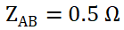

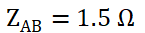
,



impedance to the right of (A, B)
at ,
at ,
Sign in to see the solution
Log in to view the explanation, track your attempts, and keep your progress.
Sign in to Unlock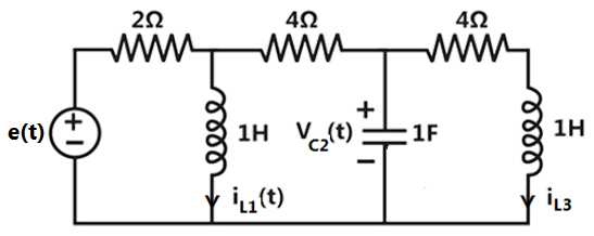
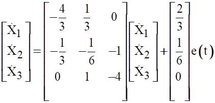
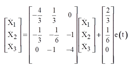
For the circuit shown in the figure is choose state variables, to be ,,




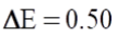
If , , , , then what would the total energy dissipated in the resistors in the interval be?





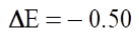
State equations
Sign in to see the solution
Log in to view the explanation, track your attempts, and keep your progress.
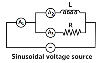
Sign in to UnlockIn the given figure, , and are ideal ammeters. If and read 3 A and 4 A respectively, then should be read



Sign in to see the solution
Log in to view the explanation, track your attempts, and keep your progress.
Sign in to UnlockThe current, i(t), through a resistor in series with an inductance, is given by


The RMS value of the current and the power dissipated in the circuit are:
A, 410 W, respectively

A, 350 W, respectively

5 A, 250 W, respectively
11 A, 1210 W, respectively
Sign in to see the solution
Log in to view the explanation, track your attempts, and keep your progress.
Sign in to UnlockA series R-L-C circuit has a Q of 100 and an impedance of at its resonant angular frequency of radiation/sec. The values of R and L are:


R = ___________ ohms, L = _________ H.
Sign in to see the solution
Log in to view the explanation, track your attempts, and keep your progress.
Sign in to UnlockA series RLC circuit consisting of , and , is connected across an a.c. supply of 200 V rms. The rms voltage across the capacitor is






Sign in to see the solution
Log in to view the explanation, track your attempts, and keep your progress.
Sign in to UnlockA generator of internal impedance, , deliver maximum power to a load impedance,, only if . (True=1, False=0 )



Sign in to see the solution
Log in to view the explanation, track your attempts, and keep your progress.
Sign in to Unlockrepresents the input impedance of a network. ( True =1 , False=0)

Sign in to see the solution
Log in to view the explanation, track your attempts, and keep your progress.
Sign in to UnlockThe response of an LCR circuit to a step input is If the transfer function has
(A) Over damped
(B) Critically damped
(C) Oscillatory
(1) Poles on the negative real axis
(2) Poles on the imaginary axis
(3) Multiple poles on the positive real axis
(4) Poles on the positive real axis
(5) Multiple poles on the negative real axis
Sign in to see the solution
Log in to view the explanation, track your attempts, and keep your progress.
Sign in to UnlockIn the series circuit shown in figure for series resonance, the value of the coupling coefficient K will be
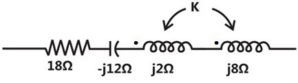
Sign in to see the solution
Log in to view the explanation, track your attempts, and keep your progress.
Sign in to UnlockIn figure, , and are ideal ammeters? If reads 5A, reads 12A, then should be read.
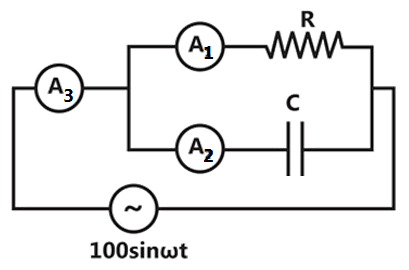
Sign in to see the solution
Log in to view the explanation, track your attempts, and keep your progress.
Sign in to UnlockFor the series R-L-C circuit of figure, the partial phasor diagram at a certain frequency is shown in figure, The operating frequency of the circuit is:
Sign in to see the solution
Log in to view the explanation, track your attempts, and keep your progress.
Sign in to UnlockIn a series RLC high Q circuit, the current peaks at a frequency
Sign in to see the solution
Log in to view the explanation, track your attempts, and keep your progress.
Sign in to Unlock