Control Systems
Transfer Function
Practice questions from Transfer Function.
27
Total0
Attempted0
Correct0
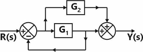
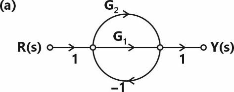
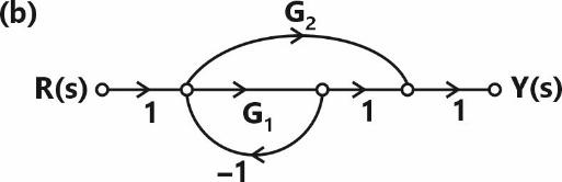
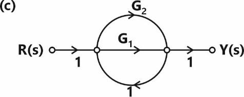
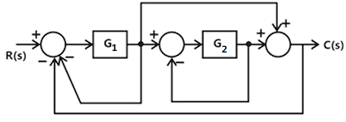
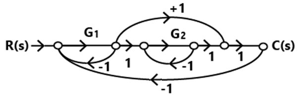
IncorrectConsider a system represented by the block diagram shown below. Which of the following signal flow graphs represent(s) this system? Choose the correct option(s).
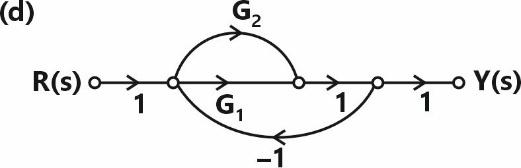
Sign in to see the solution
Log in to view the explanation, track your attempts, and keep your progress.
Sign in to UnlockIn the following block diagram, and are two inputs. The output is expressed as




. and are given by



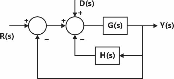
and


and


and
and
Sign in to see the solution
Log in to view the explanation, track your attempts, and keep your progress.
Sign in to UnlockThe block diagram of a feedback control system is shown in the figure.
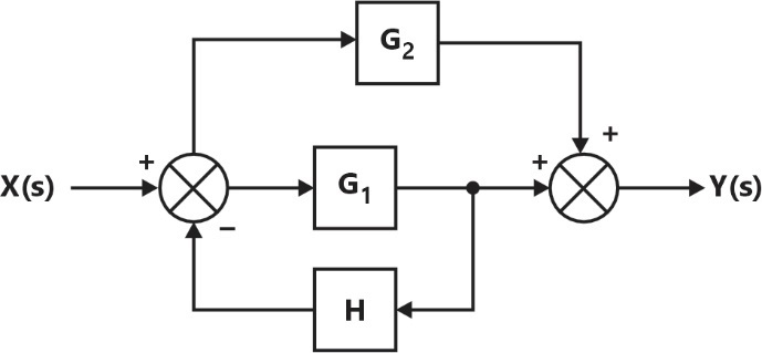
The transfer function of the system is





Sign in to see the solution
Log in to view the explanation, track your attempts, and keep your progress.
Sign in to UnlockThe block diagram of a system is illustrated in the figure shown, where is the input and is the output. The transfer function is



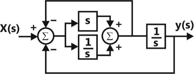




Sign in to see the solution
Log in to view the explanation, track your attempts, and keep your progress.
Sign in to UnlockFor the system shown in the figure, Y (s)/X (s) =
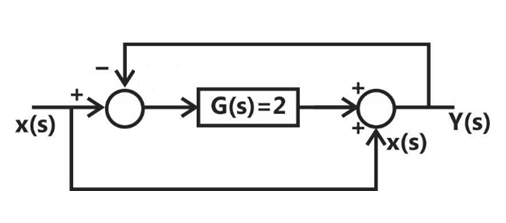
Sign in to see the solution
Log in to view the explanation, track your attempts, and keep your progress.
Sign in to UnlockThe block diagram of a feedback control system is shown in the figure. The overall closed-loop gain G of the system is
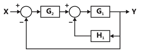




Sign in to see the solution
Log in to view the explanation, track your attempts, and keep your progress.
Sign in to UnlockFor the signal flow graph shown in the figure, the value of is

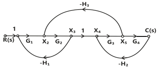




Sign in to see the solution
Log in to view the explanation, track your attempts, and keep your progress.
Sign in to UnlockFor the following system,
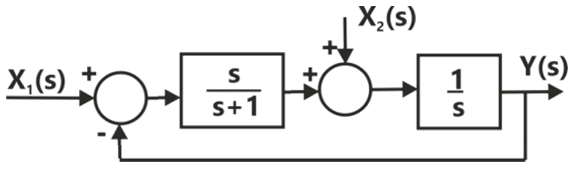
When , the transfer function is






Sign in to see the solution
Log in to view the explanation, track your attempts, and keep your progress.
Sign in to UnlockConsider the following block diagram in the figure.
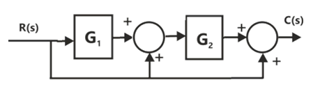
The transfer function is





Sign in to see the solution
Log in to view the explanation, track your attempts, and keep your progress.
Sign in to UnlockThe signal flow graph for a system is given below. The transfer function for this system is

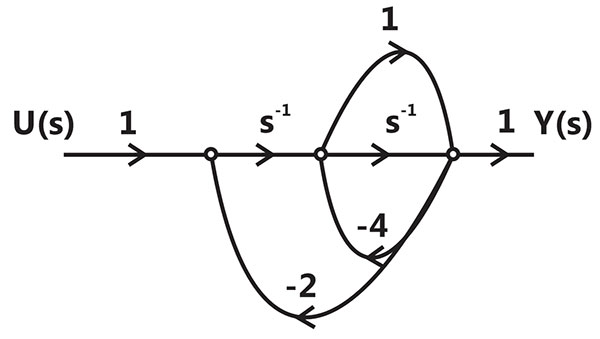




Sign in to see the solution
Log in to view the explanation, track your attempts, and keep your progress.
Sign in to UnlockThe transfer function Y(s)/R(s) of the system shown is
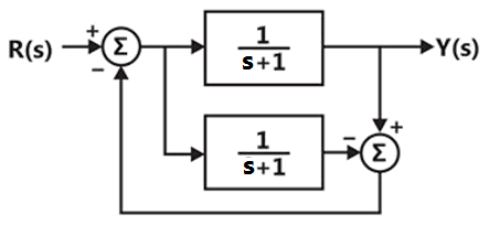
0


Sign in to see the solution
Log in to view the explanation, track your attempts, and keep your progress.
Sign in to UnlockDespite the presence of negative feedback, control system still have problems of instability because the
Sign in to see the solution
Log in to view the explanation, track your attempts, and keep your progress.
Sign in to UnlockFor the circuit shown below, the initial conditions are zero. Its transfer function is

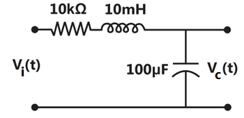




Sign in to see the solution
Log in to view the explanation, track your attempts, and keep your progress.
Sign in to UnlockConsider the signal flow graph shown in Figure. The gain is

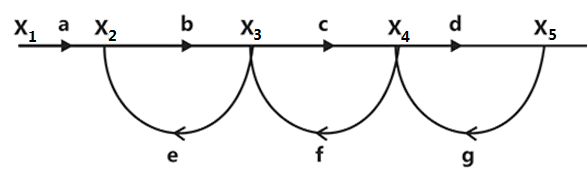




Sign in to see the solution
Log in to view the explanation, track your attempts, and keep your progress.
Sign in to UnlockThe signal flow graph of a system is shown in figure. The transfer function of the system is
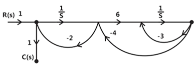




Sign in to see the solution
Log in to view the explanation, track your attempts, and keep your progress.
Sign in to UnlockThe equivalent of the block diagram in Figure is given in
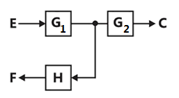
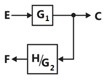
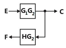
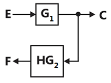
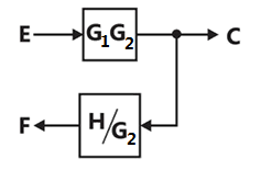
Sign in to see the solution
Log in to view the explanation, track your attempts, and keep your progress.
Sign in to UnlockAn electrical system and its signal-flow graph representations are shown in figures. The values of and H, respectively are

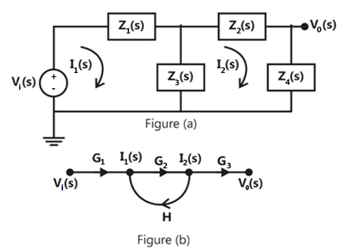
,


,


,

,
Sign in to see the solution
Log in to view the explanation, track your attempts, and keep your progress.
Sign in to UnlockThe open-loop DC gain of a unity negative feedback system with closed-loop transfer function is



4
13
Sign in to see the solution
Log in to view the explanation, track your attempts, and keep your progress.
Sign in to UnlockA feedback control system is shown in Figure.
(c) Find the number of all possible combination of non-touching loops taken two at a time.
(d) Determine the transfer function of the system using the signal-flow graph.
Signal flow graph
Total number of loops = 4
Possible combination of non-touching loops taken two at a time = 3
Transfer function of the system

Sign in to see the solution
Log in to view the explanation, track your attempts, and keep your progress.
Sign in to UnlockThe transfer function of a tachometer is of the form
Ks



Sign in to see the solution
Log in to view the explanation, track your attempts, and keep your progress.
Sign in to UnlockThe transfer function of a zero-order-hold system is




Sign in to see the solution
Log in to view the explanation, track your attempts, and keep your progress.
Sign in to UnlockIn a synchro error detector, the output voltage is proportional to , where is the rotor velocity and n equals


Sign in to see the solution
Log in to view the explanation, track your attempts, and keep your progress.
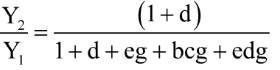
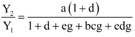
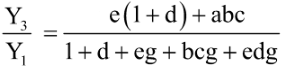
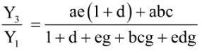
Sign in to UnlockDraw a signal flow graph for the following set of algebraic equations:



Hence, find the gains and


Sign in to see the solution
Log in to view the explanation, track your attempts, and keep your progress.
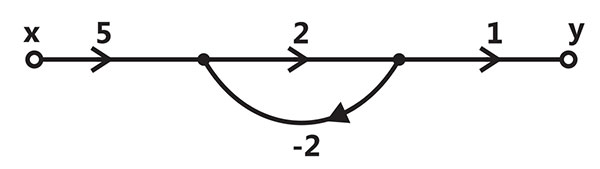
Sign in to UnlockIn the signal flow graph of the figure is y/x equals
3

2
None of the above
Sign in to see the solution
Log in to view the explanation, track your attempts, and keep your progress.
Sign in to UnlockSignal flow graph is used to find
Sign in to see the solution
Log in to view the explanation, track your attempts, and keep your progress.
Sign in to UnlockThe transfer function of a linear system is the
Ratio of the output, and input


Ratio of the derivatives of the output and the input
Ratio of the Laplace transform of the output and that of the input with all initial conditions zeros
None of these
Sign in to see the solution
Log in to view the explanation, track your attempts, and keep your progress.
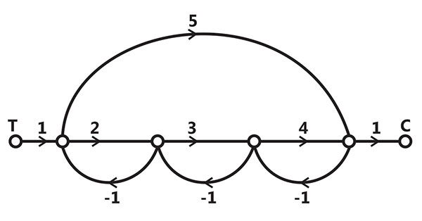
Sign in to UnlockIn the signal flow graph of Figure, the gain C/T will be




Sign in to see the solution
Log in to view the explanation, track your attempts, and keep your progress.
Sign in to Unlock