
Login to track your progress, bookmark questions, and view history.
Q#1
Oscillators
GATE EC 1997
MSQ
+2 marks
-0 marks
The figure is shows the block diagram of phase-locked-loop (PLL) in the locked condition.
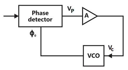
The output voltage of the phase detector is given by
,

Where = phase of the input signal, and

= the phase of the output voltage Controlled Oscillator (VCO).

The value of is 1 volt/radian,

The frequency deviation of the VCO output is,

Where = input voltage of the VCO, and

= 159.15 Hz/volt

The amplifier A is a buffer with a voltage gain of unity.
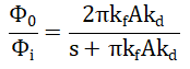
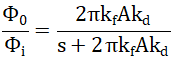
(a) Derive the transfer function.

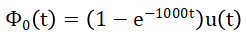
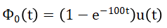
(b) Let the loop to be locked for time and radian, where u(t) is the unit step function. Determine for.


Sign in to see the solution
Log in to view the explanation, track your attempts, and keep your progress.
Sign in to Unlock
Login to keep track of your progress with the tool with daily goals, questions preparation and more.
Browse Practice Questions by Chapters / Topics in Browse Practice Questions by Chapters / Topics in GATE Electronics and Communications
Total Questions
Attempted
% Attempted
Correct
% Correct
Login to keep track of your progress with the tool with daily goals, questions preparation and more.
| Topic | Questions | Attempted | Correct | |
|---|---|---|---|---|
| Network Analysis | 273 | 0 | 0 | |
| Electronic Devices | 224 | 0 | 0 | |
| Analog Electronics | 395 | 0 | 0 | |
| Digital Electronics | 352 | 0 | 0 | |
| Signals and Systems | 263 | 0 | 0 | |
| Control Systems | 264 | 0 | 0 | |
| Communication System | 340 | 0 | 0 | |
| EMFT - ECE | 273 | 0 | 0 | |
| Engineering Mathematics | 280 | 0 | 0 | |
| General Aptitude | 240 | 0 | 0 |